Electro Tech is an online community (with over 170,000 members) who enjoy talking about and building electronic circuits, projects and gadgets. To participate you need to register. Registration is free. Click here to register now.
Welcome to our site! Electro Tech is an online community (with over 170,000 members) who enjoy talking about and building electronic circuits, projects and gadgets. To participate you need to register. Registration is free. Click here to register now.
Hello All,
My Pfaff 1222 E is running very slow. I have had it back to the repairman that I bought it from several times. I have decided to replace all of the electronic components.
I live in a remote part of Western Australia and just finding the time to take it to a repairer is an issue.
I went through the Drachenforum site https://www.drachenforum.net/index....=1&s=49e0ca760e0bb2a96b829f583260d1ddbcc2a5cb
And used Mr Kendrix post about alternative components. After a lot of cross referencing I was able to by all of the components through one company.
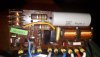
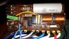
I have some questions on the Drachenforum circuit C2 is labelled 01uF 400v.
Is that 1uF or 0.1uF?
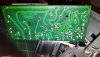
R 10 is labelled as 710k I cant get that size any more. The options now are 680k or 820k which one should I use?
I can provide a excel file of the alternate or substitute components if any one is interested.
Regards Whitworth
C2 looks like 0.1uF. You can see it in the photo at the start of the thread and post #81. A cap like that wouldn't be 1uF AFAIK. The drawings on drachenforum agree.
There's no such thing as a 710k resistor. The standard series have been around since long before that sewing machine was made. Also note it's in series with the gate of some kind of thyristor - it wouldn't be so high. Comparing the schematic on page 7 with the PCB layout on page 1, it looks like whoever drew the schematic made a typo and it's actually 10k.
This site uses cookies to help personalise content, tailor your experience and to keep you logged in if you register.
By continuing to use this site, you are consenting to our use of cookies.