Continue to Site

Welcome to our site!

Electro Tech is an online community (with over 170,000 members) who enjoy talking about and building electronic circuits, projects and gadgets. To participate you need to register. Registration is free. Click here to register now.

  • Welcome to our site! Electro Tech is an online community (with over 170,000 members) who enjoy talking about and building electronic circuits, projects and gadgets. To participate you need to register. Registration is free. Click here to register now.

Is the output of the Class E Amp. sinusoidal?...I ask coz...

Status
Not open for further replies.

Rasengan

New Member
I used this class e software from : http://tonnesoftware.com/ to get the values for the components for a freq of 100Mhz, Power output of 200mW, supply volatge 12V , Q = 5 , the inductor connected to the 12V I used 1nH and a load of 50ohms.

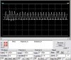
I simulated the circuit but all I get at the output are resonances dying, shouldn't I be getting a sinusoidal waveform? and if not what do I need to add to get a sinusoidal waveform?, will the amplitude of the sinusoidal waveform be constant?

I thank you for your time for reading my post
 
I'ne no confidence in simulators, what makes you think it's performing correctly?.

I don't see how you can get a decaying pulse from that circuit, assuming it's designed correctly! - the incoming squarewave (at 100MHz in your case) will cause the output tuned circuit to ring. It can't decay, because the next pulse appears before it has time to.
 
Thanks nigel

I had the input signal to 100Khz instead of 100Mhz, this is intresting so this circuit will only give an oscillation with a constant amplitude at particular freqs, Here r pictures at different freqs:

Values I used:

Vdc = 6V
Lchoke = 8nH
Shunt Capacitor = 2.9237pF
Series Capacitor = 4.136pF
Series Inductor = 612.429nH
Rload = 100ohms

Is there any way to make the circuit get an oscillation with a constant amplitude at any freq in the range of 300MHz to 2GHz?

Then I changed the value of the Lchoke to 3nH and I got a good oscilaltion with a constant freq and amplitude for the 1GHz input. (I tried to attach the picture of it but it didn't want to, it is like I couldn't attach more than 3 attachments).

If I want an input freq of 200KHz and an output oscilation with a freq of 500MHz with constant amplitude and freq, can it be possible with the class e amplifier? and if yes, how?
 

Attachments

  • 1ghz.jpg
    1ghz.jpg
    8.7 KB · Views: 555
  • 500mhz.jpg
    500mhz.jpg
    10.4 KB · Views: 543
  • 350mhz.jpg
    350mhz.jpg
    8.7 KB · Views: 544
Hi Ras,
You don't have an oscillator circuit, you have an amplifier with a tuned load that rings and decays in amplitude like a bell, until it is hit with an input again.

If you take a 200KHz signal with a rise-time that is fast enough, and feed it to your tuned 500MHz amplifier, the tuned circuit must ring and decay for 2500 cycles before the next input pulse which is impossible.

If you want a frequency range from 300MHz to 2GHz to have a constant amplitude, you must also tune the circuit continuously by changing both the L and the C to keep the Q constant. Very impractical.
 
Rasengan said:
If I want an input freq of 200KHz and an output oscilation with a freq of 500MHz with constant amplitude and freq, can it be possible with the class e amplifier? and if yes, how?

I wouldn't have thought so, this type of RF amplifier relies on being tuned to the output frequency, with the ringing of the tuned circuit generating the required frequency. It's commonly used as a frequency multiplier, where you enter one frequency, and get a multiple of it (usually two or three times) from the output.

Most VHF/UHF transmitters work in that way, for example 2M transmitters (144MHz) often use 12MHz crystals, and multiple them in a number of stages to 144MHz.

You requirements seem rather unusual?, what are you trying to do?.
 
Thanks for both of your replies

I'm studying electronics communications and I have a big ass. on the class E amplifier and applications. I also have to come up with some new application for this amplifier. (Ironic I'm not too good in electronics and I choose this course but I like it is quite interesting and I'm hoping that I'll get better understanding)

I know it not an oscillator but it does give out an oscillation, no?....maybe not a perfect sine wave but very close.

Can I say that this class E amplifier emulates an oscillator?

Can this amplifier be used as an oscillator in a transmitter?

Which types of modulations would be most suited with this amplifier?

So if I want an input square wave signal with a 200 KHz, what would be the max freq that I can get at the output? And which components in the circuit would affect the output frequency?

components spec:

Vdc : 6V
Q = 5
Inductor choke: 7nH
Shunt capacitor : 2.9237pF
Series capacitor : 4.136pF
Series inductor : 300nH
Rload : 100ohms

Note: Once the amplitude becomes constant it stays that way.
In the picture below the input freq is 250MHz and output is also 250MHz.

Nigel Goodwin wrote: “It's commonly used as a frequency multiplier”

The freq is not multiplying?

I apologize if I asked similar questions to my previews messages but it is coz I didn't quite understand your answer/s.
 

Attachments

  • 500mhz_849.jpg
    500mhz_849.jpg
    46.8 KB · Views: 524
Rasengan said:
I know it not an oscillator but it does give out an oscillation, no?....maybe not a perfect sine wave but very close.

Can I say that this class E amplifier emulates an oscillator?

No, because it's not, it's simply amplifying a pulse, and resonating a tuned circuit.

Can this amplifier be used as an oscillator in a transmitter?

No, because it doesn't oscillate.

Which types of modulations would be most suited with this amplifier?

This sort's of stages are commonly used for FM, or AM (using high level amplitude modulation of the output stage). You can't use them for SSB (or low level AM) because it's not a linear amplifier.

So if I want an input square wave signal with a 200 KHz, what would be the max freq that I can get at the output? And which components in the circuit would affect the output frequency?

components spec:

Vdc : 6V
Q = 5
Inductor choke: 7nH
Shunt capacitor : 2.9237pF
Series capacitor : 4.136pF
Series inductor : 300nH
Rload : 100ohms

Both the capacitors, and both the inductors, will affect the resonant frequency - the two in series look to be a series resonant circuit, and the other two a parallel resonant circuit.

Note: Once the amplitude becomes constant it stays that way.
In the picture below the input freq is 250MHz and output is also 250MHz.

Nigel Goodwin wrote: “It's commonly used as a frequency multiplier”

The freq is not multiplying?

It depends on how you use it, the output frequency will be that specified by it's resonant frequency (assuming the input frequency is capable of exciting the circuit). If your output is tuned to 100MHz, input a frequency of 50MHz will double it to 100MHz (2nd harmonic), likewise 33MHz input will triple to 100MHz (3rd harmonic). If you input 100MHz it won't multiply, just amplify.
 
I know an osicllator is composed of a resonator and an amplifier and then has to be closed loop (from output of amplifier to input of the resonator).

Now I have the amplifier (class E), what do I add to this amplifier to make it an oscillator? .....do I add a resonator (parallel, series, lumped)? and then a close loop? if yes where excattly do I add this resonator.

Note : To help u understand my questions say I want to make an FM using a class e amplifier. For this I need an osicllator (I want to use a class e amplifier but I still need a circuit to make it an oscillator right?) after this, to make it an fm transmitter, I need to add some capacitor be it in series or in parallel to the capacitor that decides the autput frequency to make it an FM and then maybe add a FET. for example (if parallel capacitors, C1 & C2) so when FET is on parallel capacitors add (C1 + C2 - give output freq f2) and when FET is OFF only one capacitor is in use (C1 - give output freq of f1)

By the way I'm getting confused as what is an oscillation and what is the sinusoidal output waveform of the class e amplifier I thought any sinusoidal waveform that u can vary the freq is an oscillation.
 
Hi Ras,
1) To make your amplifier an oscillator, first you must determine which class of operation it will be.
a) Class-A is the most linear but since the transistor conducts all the time, it uses a lot of power and heats-up.
b) Class-B is with 2 transistors.
c) Class-C is when the transistor is turned-off most of the time and conducts heavily for a moment. It is very efficient but transmits many strong harmonics.
d) Class-D is a switching class used for power supplies and audio amplifiers, not radio frequencies.
e) I don't think there is a class-E, just the sim program you have with that name.
The class of an oscillator is determined by the transistor's bias.

2) To "close the loop" of an amplifier to turn it into an oscillator, the circuit can be Collipits or Hartley, deterined by whether its positive feedback is provided by center-tapped capacitors or a center-tapped inductor. I can't remember what it's called but you can also cap-couple its tuned collector output to its emitter input.

3) To FM modulate a high frequency oscillator you can connect a voltage-controlled-capacitor (vari-cap diode) across its tuned circuit. Frequently an ordinary reverse-biased diode will work. Change the voltage across the diode and its capacitance will also change, which changes the resonant frequency of its tuned circuit.

4) An oscillator is an amplifier with a gain of 1 or more and positive feedback so it can continue to oscillate without any extrernal input except supply power.

I hope this helps you understand and that I presented it all correct.
 
Status
Not open for further replies.

New Articles From Microcontroller Tips

Back
Top