Super-Dave
Member
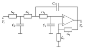
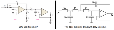
I am TRYING to build a 5 band audio spectrum analyzer for my car. I'm still in the design phase, working out resistor & capacitor values for the bandpass filters. I've chosen to go with 3rd order(single op-amp) Sallen Key low pass filters cascading into a 3rd order(also single op-amp) Sallen Key High pass filters due to their steep roll-off and flat pass band characteristics, but also reduce the component cost, complexity & real estate needed for the circuit board layout. I intend to use one quad op-amp as a buffer, and a single quad op-amp for each bandpass (this is going to be a stereo display, with left & right being handled by each half of the quad op-amp). This way I'll only need a total of 6 op-amp chips. I've found numerous websites to help me calculate the low pass & high pass filters, yet most of them spit out insane values that I don't possess in my assortment kits.
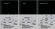
However, I have found one site that will crank out actual values I do have (mostly), the final results are close to the frequencies I want and it even shows a bode plot.
http://sim.okawa-denshi.jp/en/Fkeisan.htm
It even tells me if it oscillates and at what frequency.
A couple questions I want to know is:
1) Is oscillation bad for an audio filter? Will it create wonky strobing or glitchy performance in the LED display? Or is it just a momentary transient thing that I need not be concerned with? This is just for a visual display, not speakers so if there's distortion, I won't hear it.
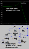
2) I've discovered that I can input MATCHING values (all caps & resistors being the same), and it won't oscillate, but the bode plot no longer resembles a sharp 3rd order response. The "knee" frequency at the -3db point is right, but it doesn't give a sharp enough dive for my liking. Or maybe I don't understand how to read it properly, the frequencies are listed in scientific notation, not actual hertz. Can you make cascading filters (low pass or high pass) with matching values and get the performance desired?
Thank you in advance for your replies.
Super-Dave
However, I have found one site that will crank out actual values I do have (mostly), the final results are close to the frequencies I want and it even shows a bode plot.
http://sim.okawa-denshi.jp/en/Fkeisan.htm
It even tells me if it oscillates and at what frequency.
A couple questions I want to know is:
1) Is oscillation bad for an audio filter? Will it create wonky strobing or glitchy performance in the LED display? Or is it just a momentary transient thing that I need not be concerned with? This is just for a visual display, not speakers so if there's distortion, I won't hear it.
2) I've discovered that I can input MATCHING values (all caps & resistors being the same), and it won't oscillate, but the bode plot no longer resembles a sharp 3rd order response. The "knee" frequency at the -3db point is right, but it doesn't give a sharp enough dive for my liking. Or maybe I don't understand how to read it properly, the frequencies are listed in scientific notation, not actual hertz. Can you make cascading filters (low pass or high pass) with matching values and get the performance desired?
Thank you in advance for your replies.
Super-Dave