Continue to Site

Welcome to our site!

Electro Tech is an online community (with over 170,000 members) who enjoy talking about and building electronic circuits, projects and gadgets. To participate you need to register. Registration is free. Click here to register now.

  • Welcome to our site! Electro Tech is an online community (with over 170,000 members) who enjoy talking about and building electronic circuits, projects and gadgets. To participate you need to register. Registration is free. Click here to register now.

Is it possible to make a mic preamp that only works with sound card dc output

Status
Not open for further replies.

Fluffyboii

Active Member
Hi,
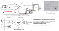
A year ago or so I made a microphone preamp with tl071 when I wasn't very good at making electronic circuits. It used a lithium ion battery, a boost converter to boost that up to 30V or something like that and feed that to the op amp which was audioguru's design which had a middle point so that op amp could function with a single sided supply. It was pain to get it working without noise that was generated from the boost converter and everyone was telling me to use one or two 9V batteries but I didn't want it because 9V batteries suck and they are expensive. But at the end, my rechargeable setup use to last 1 week with a single charge and it was working fine. I used it for a long time with both electret and dynamic microphones. Unfortunately my father lost it while "organizing" my stuff while I was at college so I don't know where it is.

Anyway at the dorm I use a single electret microphone that is directly connected to a USB-C to 3.5mm jack converter with an extension cable like this for the sake of easy usage when I rarely need it:
1671237492992.png

This works because sound card inside the converter provides some DC voltage about 2.1V to the microphone and it's internal amplifier has barely enough gain to make it sound acceptable when sensitivity is full on my computer without software boosting. Of course not all sound cards like this setup. From my experience any USB to 3.5mm sound card works with something like this but integrated ones that are in desktops and laptops have low gain so additional software boost is required which makes it sound awful. But all sound cards I tested had 2-3V bias in them so if there was a way to use that voltage for an amplifier that went between the mic and the sound card while biasing the mic as well it could be improved greatly.

For example the extension cable I use picks up some AC signal from my desk lamp because we still use flourecent lamps at dorms. If I used a differential amplifier I would be technically able to get rid of it while giving me extra gain and possibly sound quality. And this idea unfortunately got stuck in my head.

I don't want to look for low voltage op amps since they are usually work as low as 2.5V but I did not come across something with 2V min working voltage and with the single sided supply it would be even worse. So I started looking for a full discrete design.

When I checked the output of this capsule It was peaking about 100mV. Since I technically don't need additional gain with my sound card I can keep the gain low on the diff amp and focus on getting good CMMR. I immediately realized it wouldn't be possible to amplify 100mV signal with a amplifier that had no feedback since it would clip to a nice square wave. So I used some feedback to both increase input resistance and decrease the gain to something about 4 with 20K input resistors. If I find a 22k double pot for example I can make the gain adjustable on both inputs and maybe even make it be useful for dynamic mics that require much more gain. I do have 1M double pots so maybe tapering (putting parallel resistor with pot) could work?
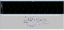
For now with no input resistors to decrease gain it gets about 35 times max gain. CMMR is about 50dB which is more than enough. Current consumption is quite low about 250uA at 2V so hopefully sound card output will be able to feed it. I messed around with values a little and found something like this is ideal.

1671239455524.png


It works well with different input voltages. I am aware that I can replace bottom right transistor with a voltage divider and if I build this in real life I may make it with a trimpot for better adjustment. Load resistors can be replaced with PNP transistors to perhaps increase open loop gain but as it is I find it satisfactory.

Two important questions I have right now before trying this on a breadboard or something like that.
How will I get differential output from electret mic.
1671239226758.png

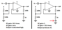
I saw this and I wonder if I can pick a resistor value to get something I can apply at the two inputs. Or can I use two electret microphones to get two similar signals. But if I used two mics that gave the same output it would be cancelled by the differential amplifier so one of them would need a 180 degree phase shift. Can these problems be relieved?

Second is getting the output. Should I use one of the differential outputs like a single ended output. Or should I have another circuit to convert differential to single ended output? I think I am only losing gain if I do the first one.
I think for making this work with a dynamic mic which requires about 200 times gain I would need PNP transistors or another stage too boost the gain. At that point I would have litteraly made a bad op amp that tolerates low voltages.
Even if I can't make this directly work without any batteries from the sound card I can always connect 2AA batteries to it I guess.

LM386 looks similar at the input side ignoring the darlington pairs. I started seeing differential amplifiers everywhere after learning about it. Are they they useful?
1671242379360.png
 

Attachments

  • 1671238951777.png
    1671238951777.png
    94.4 KB · Views: 169
  • Draft4.asc
    3.1 KB · Views: 146
Last edited:
This is the circuit I have in mind for making a pre-amplifier to replace my old one.
The resistors from input (tip) to ground are way too low. As soon as you plug in a mic (which links tip & ring), the power supply is halved.

If anything at all, use eg. 100K or 1M just to prevent the inputs floating.

I'd also change the gain control to give individual control to each channel.

You cannot properly use a two-terminal electret capsule in any way other than with the negative side grounded - that's the screening can as well.

If you need a direct differential output, get three-terminal electret capsules. Those can be used with equal source and drain resistors, with the can (and electret element common) still grounded.
Examples:

primo-em204n-cardioid-electret-microphone.jpg


ps. The correct way to use an opamp driving in to a decoupling cap is to add a low value resistor, eg. 47 Ohms, directly in series with the output pin.
 
The resistors from input (tip) to ground are way too low. As soon as you plug in a mic (which links tip & ring), the power supply is halved.

If anything at all, use eg. 100K or 1M just to prevent the inputs floating.
Is it the 4.7K resistors? Probably adding a double contact switch to change inputs makes more sense in that case. If it is another resistor, I can't see it can you tell its number on the schematic.
I'd also change the gain control to give individual control to each channel.
Multiple pots to change gain then. I have 1M double pot but I guess 1M as feedback resistor would be too much. Maybe I can find lower value double pot to change differential op amps gain as well. Or just use the spare Op amp as a inverting amplifier at the end and use a regular pot to change it's gain.
Each channel so feedback resistor of the input Op Amps right. So there would be 3 pots one for overall gain and two for different channels, right?

If I am buying capsules I would rather get a condenser capsule and make a phantom supply to have something great. I will look if I can get those electret capsules locally though.

They work when they are not grounded though. It is just that their own gain drops too much and they require about 100 times gain to get back to their original levels.

Would turning one of the capsule back give me reversed signal from it. I mean phsically placing it 180 reverse so one mic is looking up and other down. Since they are not directional I wounder if it would work. Then I can ground them directly.
 
Last edited:
Why would anybody buy a 3-pins microphone with no manufacturer's name and no detailed audio specs??
Does ebay think we are stupid?
 
Is this what you are talking about?
Yes it doesn't look anything like textbook examples.
1671390459231.png

These resistors existence also confuse me.
1671390606880.png

So the capacitor makes DC gain 1 since it acts like open circuit hence making it a buffer but acts as an short so the AC gain is 470K/2.2K right? Makes sense when I think about it.
1671390758040.png

Actually missing RC filter was this you pointed out a year ago.
 
Last edited:
A wall wart power supply could have hum and a weak 9V battery could have its voltage jumping up and down with the circuit signals. Then the 9V must be filtered so that the preamp does not amplify the noise.
 

Attachments

  • opamp biasing filter.png
    opamp biasing filter.png
    129.3 KB · Views: 143
It looks like turning one microphone around does give a inverted signal compared to the mic that is facing forward. I need to check it with an oscilloscope since I gave back the one I borrow, I will have to go to lab and see it myself but looks like I can make a nice desk microphone/preamplifier and put in a nice box. There is always one thing that bother me though. I want my mic powered from my computer. Whenever I try using USB power I get immense noise, probably because my power supply inside my desktop PC is cheap and it is not supplying clean 5V. And I know that there is always high frequency noise when boost converters are involved. Is there a way to eliminate this problem. I assume one way would be to put a huge inductor choke to get rid of it, but that would create a voltage spike when device is powered on.

I don't know how commercial audio products don't face this issue.

Linear converters filter the ripple that is created by full bridge rectifier. Can they also filter high freq garbage that is created by boost converter. Is it viable to use a boost converter to get 20V out of 5V then use a 15V linear converter to get clean 15V?
 
Last edited:
A large part of the noise will be due to ground currents, in a PC. I use an isolating transformer to break the ground back to or from the audio port, when connecting to equipment that has external power connections.

Or you could use an isolated converter from the USB supply, so that ground is broken rather than the audio one.

USB audio devices don't gave a problem because they have a single ground and the audio to & from the PC is digital, so not sensitive to noise like analog audio.
So should I look for isolated boost converter topologies. Maybe having a simple oscillator then having a transformer with low ratio to increase it a bit so I can use a fullbridge rectifier to get higher voltage DC would work. Colpitts oscillator seemed to work at as low as 5V but needs buffering. Or perhaps digital triangle wave converted to analog sine-ish wave with filtering could work. I am sure there are better options though.

Looks like there are premade through hole isolation Dc-Dc converters about 5USD.
 
Last edited:
My teacher want me to make a differential amplifier ECG measurement device with 3 electrodes and AD620 Differential Op Amp. Should I open another post for it or write about it here since diff. amps. been talked about here.
Something like this:
1671719325062.png

I was thinking of how the hell I was supposed to use a diff amp which has 2 inputs to measure 3 inputs. This is really interesting since it is using the gain setting in an unique way.
I need it to operate at 5V from Arduino so I will use a TL081 to set the middle point.
Lab document says use op amp for setting middle point but it seems to be not necessary.
1671720807441.png
 
Last edited:
I was thinking of how the hell I was supposed to use a diff amp which has 2 inputs to measure 3 inputs.
It's only the difference between two inputs, the arm (or chest) electrodes.

The third electrode is used to "drive" the sensor<>body voltage and keep the average electrode voltage well within the opamp common-mode range.
 
The third electrode cancels hum and noise picked up by the main electrodes.

I guess you did not read the datasheet for the AD620. it is not a simple differential amplifier, instead it is an Instrumentation amplifier.

Lookup "instrumentation amplifier" to see that has 3 opamps in it plus a few very well matched resistors.
The minimum recommended supply for a TL081 is +5V plus -5V, maybe it can feed the 3rd electrode..
 

Attachments

  • AD620.png
    AD620.png
    65.7 KB · Views: 129
The third electrode cancels hum and noise picked up by the main electrodes.

I guess you did not read the datasheet for the AD620. it is not a simple differential amplifier, instead it is an Instrumentation amplifier.

Lookup "instrumentation amplifier" to see that has 3 opamps in it plus a few very well matched resistors.
The minimum recommended supply for a TL081 is +5V plus -5V, maybe it can feed the 3rd electrode..
Isn't instrumentation amplifier is just 2 more op amps added to the differential amplifier to increase it's performance.
1671753603191.png

I know what an instrumentation amplifier is. I just referred it as differential amplifier since it acts like and consists one. I made one out of TL074 at #16. Anyway lab report says we were supposed to use OPA344 for subsequent amplifier but since I attend to a poor college that only requires a lifetime worth amount of money of an average family for 4 years of education for it's paid students they can not resource enough funds to purchase appropriate components for labs. For this reason TL081 will have to work with +-2.5V. It will be sad and maybe have distortion but will try.

One difficult thing to understand for me is the connection of gain setting pin 8 and 1 in my previous post. Output is connected to the electrode. It looks like it is set to 7 times gain by default.

Checking the datasheet more reveals a lot of information. It seems like it doesn't have jfet inputs but still has high input resistance thanks to some very high beta thing it got going on. I don't have enough time to check it throughly since I have exams coming up but it is interesting that they provided us these since it seems like it is not super cheap either. I was expecting bunch of half dead LM741s.
 
The minimum recommended supply for a TL081 is +5V plus -5V, maybe it can feed the 3rd electrode..
There was sale for ICL7611 Mosfet OpAmp so I bought 3 of them. It has worse bandwidth and slew rate compared with TL071 but works at voltages as low as +-1V. I am bad at reading datasheets but it looks like It can be used for audio purposes and it also uses very low current. It should be fine for that op amp to connect leg and gain setting for AD620. It costs like 70 cents right now. Should I buy more. I don't know when I may need low voltage op amps but since they are hard to come by I was wondering if I should stock some for future. And I also have the same question. Can it be used for mic preamplifier that only feeds from line voltage. (Looks like it can't be used)

For best performance it needs to be set at 1mA iQ.
Looks like it normally costs over 6 Euros but I know this supplier is selling legitimate products since it is the biggest electronic supplier in Turkey.
Texas Instruments Differential Op Amp single supply article says I need to buffer the reference voltage and I was thinking I could use TL431 since it has a default reference voltage of 2.5V so I don't need extra resistors for 5V single supply and it is very cheap instead of using voltage divider and an OpAmp buffer.
1672651642045.png


1672651858206.png

Any ideas how I can simulate human body in LTSpice to test the full ECG circuit. And how should I pick TL431 bias resistor. Looks like people often use 330 ohms and since I am powering it with 5V using high value resistance causes current to be too low and some voltage fluctuations at the reference pin. Since TL431 is rated at 100mA maybe I can use something like 100 ohms instead.
 
Last edited:
The Maxim opamp produces a high output impedance (use a 1M load) , a high noise level and no high audio frequencies (old telephone or AM radio sounds) when its current is set low.

The AD620 instrumentation amplifier does not work with an input at the same voltage as its negative supply (both are grounded in your circuit). It needs an additional negative supply.
It is used with 5V single supply here.
Will high output impedance cause issues for leg drive. At the output it should be ok since it will feed into Arduino analog input. I will use it in high current mode. Why is got terrible specs though, if one thing I learned from Analog IC class there should be a tradeoff for something. This looks like it is straight bad except operating voltage.

I have 2 AD620 chips. Can I use one for leg drive somehow.
 

Attachments

  • Screenshot_2023-01-02-18-54-01-814_com.google.android.apps.docs.jpg
    Screenshot_2023-01-02-18-54-01-814_com.google.android.apps.docs.jpg
    399.8 KB · Views: 138
Please learn why opamps must have their inputs biased properly.
It is much easier to use an ordinary opamp as a single-input inverting amplifier than an AD620 2-inputs instrumentation amplifier.
 

Attachments

  • AD620 circuits.png
    AD620 circuits.png
    204.7 KB · Views: 132
Please learn why opamps must have their inputs biased properly.
It is much easier to use an ordinary opamp as a single-input inverting amplifier than an AD620 2-inputs instrumentation amplifier.
I wasn't going to use LTSpice model since human body is not an grounded voltage source. Single supply setup works well with a single op amp as you said but with AD620 it gets meaninglessly complicated. I will ditch the single voltage pipe dream and use two 9V batteries to get positive and negative sources instead. Or I will just fix my synth +-12V supply. There is no way I can add the middle point, bias voltage to the inputs of AD620 and that leg driving op amp anyway. Human heartbeat has a low frequency so I can not use capacitors to isolate DC bias. The way Ti manual explains doesn't work because inputs are connected to the patient. There is no way to get it working easily I think.

Only thing that bothers me is that teacher said to use 5V at the original document. Even though he confirmed he would accept if I use double external supply I still think there must be an easy way of setting it up for only 5V since he wrote it like that. Arduino outputs about 4.6V. Only way I can think is using a oscillator and generating some AC voltage, then splitting it to positive and negative.

Actually I should make a circuit to generate double supply from 5V dc. It would save me from a lot of headache. The Radio Amateur Hand Book has a circuit that can be used for this.
 
Last edited:
The patient and the circuit's ground must never be connected to earth.
The circuit's 0V ground voltage is near half the supply voltage when there is a positive and negative supply.
Then the amplifier inputs are biased so that they work.
 
I wasn't going to use LTSpice model since human body is not an grounded voltage source. Single supply setup works well with a single op amp as you said but with AD620 it gets meaninglessly complicated. I will ditch the single voltage pipe dream and use two 9V batteries to get positive and negative sources instead. Or I will just fix my synth +-12V supply. There is no way I can add the middle point, bias voltage to the inputs of AD620 and that leg driving op amp anyway. Human heartbeat has a low frequency so I can not use capacitors to isolate DC bias. The way Ti manual explains doesn't work because inputs are connected to the patient. There is no way to get it working easily I think.

Only thing that bothers me is that teacher said to use 5V at the original document. Even though he confirmed he would accept if I use double external supply I still think there must be an easy way of setting it up for only 5V since he wrote it like that. Arduino outputs about 4.6V. Only way I can think is using a oscillator and generating some AC voltage, then splitting it to positive and negative.

Actually I should make a circuit to generate double supply from 5V dc. It would save me from a lot of headache. The Radio Amateur Hand Book has a circuit that can be used for this.
You might check my tutorial hardware, the 7660 is a standard chip for such use.

 
Status
Not open for further replies.

Latest threads

New Articles From Microcontroller Tips

Back
Top