gramo
New Member
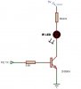
I'm building a simple IR transmitter, just wanted to know if this circuit is ok, or if it could be improved.
The IR LED has a 1.6V Forward voltage, and operates at a nominal 50mA. The closest I could get, with the below circuit, was 44.9mA, is there a way I could run it right on 50mA?
The IR LED has a 1.6V Forward voltage, and operates at a nominal 50mA. The closest I could get, with the below circuit, was 44.9mA, is there a way I could run it right on 50mA?