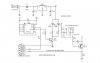
as for the transmitter part everything is ok with it.when debugging i used the function generator as a signal.
but the receiver part i got a hard time with the IR receiver....it cant receive anything data being transmit from the transmitter LED.so is there any one who can kindly help mi or give some opinion?
parts changed is:
ztx600 change to ztx300 (Darlington pair)
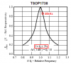
tsop1170 change to tsop1138 (38kHz)
but the receiver part i got a hard time with the IR receiver....it cant receive anything data being transmit from the transmitter LED.so is there any one who can kindly help mi or give some opinion?
parts changed is:
ztx600 change to ztx300 (Darlington pair)
tsop1170 change to tsop1138 (38kHz)