Continue to Site

Welcome to our site!

Electro Tech is an online community (with over 170,000 members) who enjoy talking about and building electronic circuits, projects and gadgets. To participate you need to register. Registration is free. Click here to register now.

  • Welcome to our site! Electro Tech is an online community (with over 170,000 members) who enjoy talking about and building electronic circuits, projects and gadgets. To participate you need to register. Registration is free. Click here to register now.

ir receiver module problem

Status
Not open for further replies.

lloydi12345

Member
I want to create an obstacle avoider mobot and I'm using this infrared receiver module. This is my schematic for the emitter

**broken link removed**
I used 120 ohms for R2 and 10uF for C1

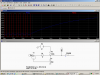
and this is my receiver schematic:
**broken link removed**
I didn't used C1 here since I'm just testing yet, I used also LM324 instead of 2n2222.

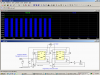
The problem is when I start to give 5v on my receiver, it receives a pulse even if the emitter is not yet powered (the visible LED lights at random sequence). Even by just moving the breadboard it makes the visible LED light.

Another problem is when I now give a power to the emitter part, even if there's no IR LED, the receiver module still recognizes the pulse lighting the visible LED.

Can you help me here? Is this one about the electrical noise?
 
The 555 causes supply current spikes of 400mA and you do not show a supply filter capacitor to smooth them.
The IR detector IC has automatic gain control like most others that reduces the gain when it receives continuous IR at 38kHz from a compact fluorescent light bulb and from your transmitter. The very poor Japanese to English translation almost tells you what all the other datasheets clearly say about your missing supply filter for the IR receiver IC and the bursts of pulses needed for good range.

In your iR transmitter, 220 ohms is much too low and 10uF is much too high for 38kHz.
 
IR switch

The detectors are pulse detectors so they need pulses at 38 Khz to work right.
Then you need to turn the pulsed back into a switch signal.
They are also sensitive to noise so use C1. Most application notes add a 100 ohm resistor between +5 and the detector with C1 at the detector.
 

Attachments

  • 38khz xmit.PNG
    38khz xmit.PNG
    56.9 KB · Views: 1,502
  • 38khz rec.PNG
    38khz rec.PNG
    46.1 KB · Views: 484
Thank you for the reply sir audioguru and ronv,

sir? in my transmitter side, what about if i change 220 ohms to 22k ohms? and 10uF to .001uF mylar? then I'll use another cap 10uF on my Vcc and Gnd? will this help? or what value of capacitors will I need?

then in my receiver side, I'm placing the capacitor .01uF.. I still don't understand on how to determine the best value for the capacitors. I hope you can give me few statements of clarifications thank you.

edit: Do I still have to utilize pin5 of 555 IC?
 
Last edited:
Thank you for the reply sir audioguru and ronv,

sir?
I am not knighted by the queen of England so I am not a SIR. I am also not from India. I am a macho DUDE!

in my transmitter side, what about if i change 220 ohms to 22k ohms?
I don't know which resistor because none are 220 ohms.
You say that R2 is 120 ohms. it sets the frequency and duty-cycle. If it is 22k then the frequency will be much lower than 38kHz.

10uF to .001uF mylar?
If C1 in your transmitter is 10uF then the frequency is very low. With 0.001uF then the frequency can be calculated or seen on the graph in the datasheet (around 33kHz but can be adjusted higher).

then I'll use another cap 10uF on my Vcc and Gnd?
Yes.

in my receiver side, I'm placing the capacitor .01uF.
No.
Use the RC circuit shown on the datasheets for European TSOPxxxx IR receiver ICs.

I still don't understand on how to determine the best value for the capacitors.
Ceramic capacitors are excellent filters for high frequencies but are useless at low frequencies. They have low values.
A film capacitor has no distortion and is non-polar. It is exxcellent for audio coupling. It has medium values. Modern ones are small and inexpensive.
An electrolytic capacitor has high values at small sizes and low costs and is a good low frequency filter. It is useless at high frequencies.
Most are polarized. The value varies a lot.
 
I am not knighted by the queen of England so I am not a SIR. I am also not from India. I am a macho DUDE!

lol does SIR sounds feminine or what? I was referring to you both with ronv. :D I'm just giving some respect for long-time forum members, but if you insist dude, I'll call you audioguru

I don't know which resistor because none are 220 ohms.
You say that R2 is 120 ohms. it sets the frequency and duty-cycle. If it is 22k then the frequency will be much lower than 38kHz.

I'm sorry I said 120 ohms because on your first reply you've seen it as 120 ohms. Therefore, the smaller the value in my R2 gives a lot faster pulse which i think exceeds 38khz and the higher the value in R2 slows the frequency , I think I'll be using 3.3k ohms,

If C1 in your transmitter is 10uF then the frequency is very low. With 0.001uF then the frequency can be calculated or seen on the graph in the datasheet (around 33kHz but can be adjusted higher).

this is what I don't have .001uF :D I still have to wait for tomorrow since I can't buy today

No.
Use the RC circuit shown on the datasheets for European TSOPxxxx IR receiver ICs.

I didn't realized that the application circuit on the datasheet was important :)
Thanks for pointing it out.

How about if I don't have any idea what my sensor module number is? I just bought it on a junkshop and they don't have any idea on how it is used. But they are sure it is still working and really it is working after trying to use it.

I learned alot from you! thank you
 
If you don't know the part number of a complicated IR receiver IC then we are just guessing about how it works.
 
Here are some links to data sheets and application notes. If you take your time and read them carefully you will be able to see what AG is talking about. Take a look and come back with questions. Right now there is no way to explain without a reference document.

TSOP-1738 datasheet and Application Note, Data Sheet, Circuit, PDF, Pinout | Datasheet Archive Look at fig. 8.

https://www.electro-tech-online.com/custompdfs/2010/10/LM555.pdf Page 4

https://www.electro-tech-online.com/custompdfs/2010/10/555an.pdf Page 3 & 5
 
Problem will also be those TSOP IR receivers have an AGC so sending a continuos data stream won't work very well.

This is an old wives tale that runs rampant on these forums! It is simply not true for all IR receivers.

If you transmit a continuous 38KHz IR carrier to a Sharp GP1u58X IR receiver, it locks on to the carrier, and sets its internal agc based on that signal level. If you then interrupt the beam for a short time (like by moving your hand or body through the beam) the receiver output pulses on the rising edge as the beam is re-established. It does this reliably, every time, with a range of > 3meters even in daylight.

The output is not DC coupled, however. The duration of the output pulse seems to be dependent on some internal time-constant inside the agc-loop as the loop re-acquires the IR signal. It works well as a beam-break detector. I use it to count runners as they run down a trail during the Wasatch 100 mile run.
 
Last edited:
If you transmit a continuous 38KHz IR carrier to a Sharp GP1u58X IR receiver, it locks on to the carrier, and sets its internal agc based on that signal level. If you then interrupt the beam for a short time (like by moving your hand or body through the beam) the receiver output pulses on the rising edge as the beam is re-established. It does this reliably, every time, with a range of > 3meters even in daylight.

Sorry, but >3m is a pretty appalling range :p

The TSOP's probably do a similar crippled range on a continuous carrier?.

Your comment about the output not been DC coupled is probably exactly what we're talking about, where you need pulses, not a continuous carrier.
 
Sorry, but >3m is a pretty appalling range :p

No, this is outdoors, in bright sunlight with only about 50mA peak current in the transmitting LED. The system runs on battery power continuously for about 2days at a time, and must be backpacked to where it is set up, so that precluded bigger batteries and higher peak LED current. If I run it at night, outdoors, the range is about 15m, which is about as good as any IR remote I have tried.


The TSOP's probably do a similar crippled range on a continuous carrier?.

Your comment about the output not been DC coupled is probably exactly what we're talking about, where you need pulses, not a continuous carrier.

For a beam break detector, modulating the transmitter with pulses, and then adding a secondary pulse-detector, filter, and output comparator is totally unnecessary.
 
Last edited:
Thank you for all of the replies you guys left here. They are really helpful!

I would like to add aditional information about my project. The LM324 comparator connected on the IR receiver module outputs a digital signal 1 or 0 directly to my microcontroller receiving it will make the motors turn right or left then, forward or backward. It will send 1 if there's an obstacle detected and 0 if there's none.

After reading through these great discussions, I learned new things. 38khz is not enough for the TSOP IR receiver module to recognize it which I thought at first that it only needs a steady 38khz pulse although there are some IR receiver modules that can function even the pulses are steady. My TSOP receiver module will only recognize 38khz when there's a turning on and turning off. From the 1st image ronv has attached in his 1st reply, the 1st 555 IC serves as switch since it sends a signal a little bit slow like 200+hz and then the next 555 IC sends the 38khz pulses.

UHmmm.. I have additional questions.

1. Input is from where? I really can't use another pin from my microcontroller.
2. Is it possible to turn on and off my 38khz without using the 1st 555 IC timer and its other components attached to it? I really wanted to have fewer components as much as possible for it to fit on my robocar.
3. TSOP recognizes the remote control I'm using, does it mean the remote control has a switching on and off on its 38khz?

Thanks! Really :D
 
Last edited:
Is it safe if I will place 10k var resistor on R4 here?
Sorry if the image is so big. I unintentionally used Quick Reply than Reply.
38khz-xmit-png.47249
 
Last edited:
To answer your questions first:

1- For it to run all the time tie the reset pin to Vcc
2- No
3- Yes, If you are using a television remote each channel has a different set of pulses.

Now the circuit:
It does work-- but, In the simulation I attached the low frequency (200 HZ) was just to show it could be turned on and off. You want the first stage to run at about 2KHZ. Your second stage runs at about 20KHZ. It would be better if it ran at 38KHZ.
Also to make the duty cycle closer to 50% (symetrical) your R4 should be small compared to R5.

From what R4 are you referring to? R4 on my image or from yours?
 
Yours. Play with some values in the equation for the timing on the 555 and you will be able to see that with your setup you can get almost a 50% duty cycle (which is good enough). Be careful not to exceed the maximum current spec for the dischage pin.
 
Yours. Play with some values in the equation for the timing on the 555 and you will be able to see that with your setup you can get almost a 50% duty cycle (which is good enough). Be careful not to exceed the maximum current spec for the dischage pin.

Okay thanks for the reply, I will try your circuit first before the circuit I got from the net.. :D
 
Sorry for the very late reply, I still did my other unfinished project. The circuit is already working for the IR LED and the IR receiver. I always place them on a separate breadboard. Now, when I place them on the same breadboard, the IR receiver keeps on receiving signals even if there's no IR LED present at the breadboard. If separated in another breadboard, IR receiver wont light if IR LED is not present on the other breadboard. Why is that so? Thanks in advance.

EDIT: This is my schematic

**broken link removed**\

J3 - J5 are the IR modules, J4 and J5 are the same, J3 is different but they all work together on breadboard.
D1- D3 are the IR LEDs

J6 is connected to the main circuit.
Pin1 is connected to power
Pin2 - Pin4 are connected to Comparator LM324 to give signal logic 0 or logic 1 when an obstacle is detected which is going to the PIC to perform tasks.
Pin5 is connected to ground
 
Last edited:
Status
Not open for further replies.

Latest threads

New Articles From Microcontroller Tips

Back
Top