Continue to Site

Welcome to our site!

Electro Tech is an online community (with over 170,000 members) who enjoy talking about and building electronic circuits, projects and gadgets. To participate you need to register. Registration is free. Click here to register now.

  • Welcome to our site! Electro Tech is an online community (with over 170,000 members) who enjoy talking about and building electronic circuits, projects and gadgets. To participate you need to register. Registration is free. Click here to register now.

IR circuit output

Status
Not open for further replies.

gatman

New Member
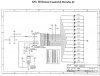
I have this test circuit for an IR reciever project, it says each of the 14 out pins used is normally held high, when the remote signal is recieved it changes the pin on chip to a low , could any body tell me what the high and low refers to (what voltage)

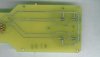
I have a circuit board (attached), that has 4 contact switches, which also uses a 5v circuit, i want to know if i can use a low out signal from the reciever circuit to trigger the the circuit in place of the contact switches,
as in tie the low outs into the 6pin jack .

Any suggestions would be appreciated

Thank You :lol:
 

Attachments

  • bedtestcircuit_1LOWRES.jpg
    bedtestcircuit_1LOWRES.jpg
    44.1 KB · Views: 578
  • bedcontrol.jpg
    bedcontrol.jpg
    26 KB · Views: 587
  • bedcontrol_bottom.jpg
    bedcontrol_bottom.jpg
    24 KB · Views: 600
Say you power the chip with 5V or the circuit has a 5 volt regulator (like the 7805). That is what voltage the outputs are held high at.

Normally it is done with a pull-up resistor when the state of the input is unknown and you want to know that the inputs is high and mke the siganl pull low.

In the outputs, and by the schematic I dare to guess that the chip held the pin high and according to what it recieves pull low. So if it doesn't receive the output pins are at 5V and when it recieves they go low, accordong to what the chip is programmed to do.

So the circuit board you have, you can use the low signal as long as you don't go over the sinking capability of the IR decoder chip. For example you will not be able to use it to hook up a motor to it. My guess is that the pin will not be able to sink mora thant 25mA...... but it is just a guess.

Ivancho
 
The circuit with the four contact switches is used to control an electric bed, i'm assuming they activate some sort of relays when pressed that turn the motors on or off, the out pins is what i want to use to take place of the contact switches that control the bed(if I can)

how do know find the sinking capability
 
According to the 89C2051 datasheet..... this Atmel can only sink 20mA of current.

I am guessing that those 4 contact switches that you are refereing to are some sort of H-bridge driver, to control a motor direction. Just guessing here!.

You are better off by using some transistors and let the transistors deal with the contacts positions, so they are able to handle the excess current. What are those contacts controlling or hooked up to?
 

Attachments

  • UCSink.jpg
    UCSink.jpg
    67.8 KB · Views: 549
Status
Not open for further replies.

Latest threads

New Articles From Microcontroller Tips

Back
Top