Continue to Site

Welcome to our site!

Electro Tech is an online community (with over 170,000 members) who enjoy talking about and building electronic circuits, projects and gadgets. To participate you need to register. Registration is free. Click here to register now.

  • Welcome to our site! Electro Tech is an online community (with over 170,000 members) who enjoy talking about and building electronic circuits, projects and gadgets. To participate you need to register. Registration is free. Click here to register now.

Inverting amplifier using AD822 op amp with schematic

Status
Not open for further replies.

max1525

New Member
I'm trying to construct the AD822 op amp to function as an inverting amplifier from a single supply. The input to the inverting terminal is 2v DC and the input will never go negative, it will either be "on" or "off".

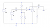
The vs+ is connected to a 12v supply rail with decoupling capacitors and vs- is connected to ground.
The non inverting is connected to a voltage divider (pair of 100k ohm resistors) to give vcc/2 as a voltage reference (6v). A filter capacitor of 10micro farads has also been connected from vcc/2 to ground.
A series resistor of 1k is connected to the input and a feedback resistor of 2k is connected between the inverting input and output of the amplifier. Knowing, vout=vin*(-rf/rseries). I would expect the output to be near -4v, given a gain of 2 and the phase change.
However the output is approximately 6v ,the same as the reference and there is no change in phase.

I feel there is a simple mistake I have done but I am yet failing to see where I may have gone wrong.

Any help would be greatly appreciated
 
Schematics is the language of electronics.
Trying to understand a circuit from a wordy description makes my head hurt.
Please post one for your circuit.
 
I have to agree with crutschow about the need for a schematic.

I entered a schematic into ltspice based on my interpretation of your description, but got a different result than you did, so something doesn't mesh.

Please post a schematic. Also, what is the source of the 2v input and how is it coupled?
 
This is a schematic of the circuit I'm using. I've changed the parameters of the circuit and it doesn't matter what values I use I still get approximately vout = vcc/2, so there seems a fundamental problem with my design/construction of the cct.

For Vin I'm using a constant 2vDc source, however when I get the basis of the cct working correctly this will be adapted to function similar to a summing amplifierwith multiple "on" / "off" dc inputs.
 

Attachments

  • IMG_0655.PNG
    IMG_0655.PNG
    75.3 KB · Views: 200
Ah ha. Just as I suspected.

The 2V DC input is AC coupled through capacitor C3. That means that that DC input voltage doesn't exist as capacitors don't conduct DC.

What you really have is a unity gain DC op-amp with 6 volts at the non-inverting input. The gain is unity because R7 is is not terminated. So you get 6 volts out.

The circuit that you have is a valid AC amplifier. If you feed an AC signal in to Vin, then you will get an AC signal with twice the magnitude at the output of the op-amp. The output signal will be inverted, and it will be centered about 6 volts (the DC ref voltage feed to the ni pin)
 
I removed the capacitor so DC will flow. As ChrisP58 said.
The (+) input is 6V.
The amplifier will try to make both inputs the same voltage. If it can.
R7 will have 4 volts across it.
R8 is 2x larger so 8V across it.
The output should be 14V. BUT it can not because the supply is only 12V.
1554915203278.png

The real question is do you want to amplify AC or DC or both??
 
Thanks for this, I'm amplifying DC.
If this circuit was to be modified to function as a summing amplifier with 6 input lines and the input to each line now being 3v DC.

Given that the feedback resistor, voltage reference and Vin (3v) will be constant for each input line. Is it possible for each input to have a different gain and Vout to range from 400mV to 6V when the only variable that can be changed is the input resistor for each input line.

This can obviously be done by using a dual supply but I'm just wondering if it's possible with a single supply? As I believe that to achieve a such wide range of voltages for Vout, Vin would need to be varied with additional components.
 
Last edited:
Status
Not open for further replies.

Latest threads

New Articles From Microcontroller Tips

Back
Top