Continue to Site

Welcome to our site!

Electro Tech is an online community (with over 170,000 members) who enjoy talking about and building electronic circuits, projects and gadgets. To participate you need to register. Registration is free. Click here to register now.

  • Welcome to our site! Electro Tech is an online community (with over 170,000 members) who enjoy talking about and building electronic circuits, projects and gadgets. To participate you need to register. Registration is free. Click here to register now.

Intuitive and mathematical ways to prove that a circuit will oscillate

Status
Not open for further replies.

hanhan

Member
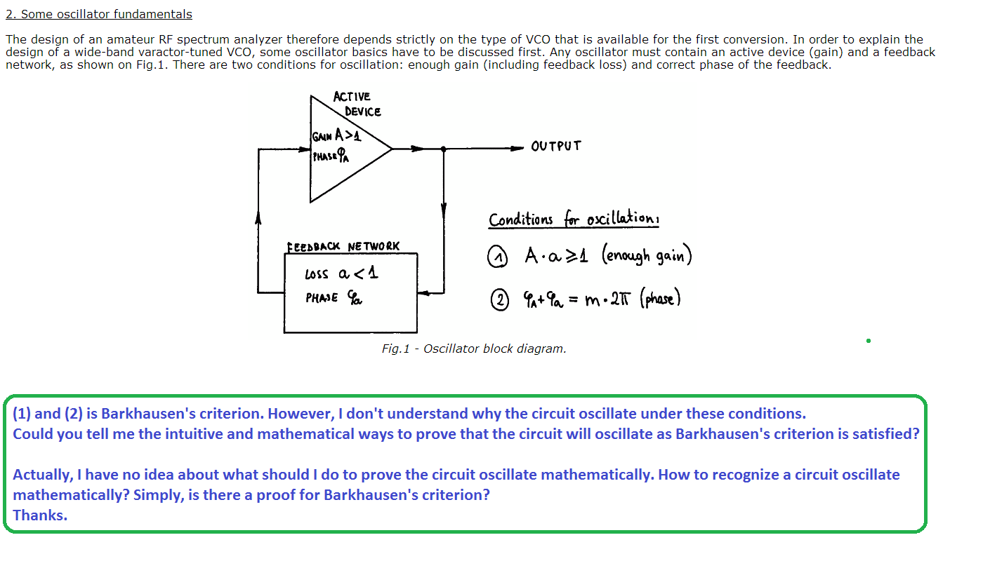
I was reading about LDO and this came across this page about Barkhausen's criterion for oscillation.
http://lea.hamradio.si/~s53mv/spectana/vco.html

Could you help me with the question in picture?

oscillation-conditions-1-png.85299
 

Attachments

  • oscillation conditions 1.png
    oscillation conditions 1.png
    90.5 KB · Views: 1,175
Or simply examine this circuit

86.png


We connect a sin wave at amplifier input, at the output we have - Vin*Ku.
Where Ku is open loop gain. Then we have a feedback network, and the voltage at point B is equal
Vb = Vout * Ku2; where Ku2 = Vb/Vout (the gain of the feedback network).
And know if we tune the feedback network to get at point B signal identical as we have at input (Vb = Vin). We can hoped that if we short B with A (red dashed line) the circuit will start automatically oscillated.
So if our open loop gain is larger or equal to 1
Va/Vb = Ku *Ku2 > 1 (this means that Va = VB) and Va and Va will have the same phase, the circuit will start oscillated.

In simply terms at some frequency, an amplifier (with negative feedback) response will have a 180° phase shift. If the gain at that frequency is greater than 1, it can result in net positive feedback and thus an unstable system.


Try read this
http://e2e.ti.com/blogs_/archives/b...an-intuitive-look-at-two-frequent-causes.aspx
http://educypedia.karadimov.info/library/acqt0131.pdf
 
Thank you, Jony.
Nice picture again! That makes sense. I have some questions.
I am reading the article. That looks interesting.

So if our open loop gain is larger or equal to 1
Va/Vb = Ku *Ku2 > 1 (this means that Va = VB) and Va and Va will have the same phase, the circuit will start oscillated.
If open loop gain is larger than 1 then the amplitude will increase unlimitedly. Should the gain is only 1?

In simply terms at some frequency, an amplifier (with negative feedback) response will have a 180° phase shift. If the gain at that frequency is greater than 1, it can result in net positive feedback and thus an unstable system.
Is this because the total phase shift is 360° then?
 
If open loop gain is larger than 1 then the amplitude will increase unlimitedly. Should the gain is only 1?
Yes in theory if gain is large then 1 the amplitude will increase unlimitedly. But in real world this is not the case, because supply voltage limits our output voltage. And this is why in real world we add automatic gain control circuit to control the amplitude.
https://www.ti.com/sc/docs/apps/msp/journal/aug2000/aug_07.pdf

Is this because the total phase shift is 360° then?
Yes, this 360° means that we have no phase shift between Va and Vb. So now our feedback is changing from negative to positive.
 
Hi,

Intuitively if you look at an amplifier with the output going back to the input it makes sense that after the initial start up if the output feeds the input and the input signal is responsible for the output signal then if the input causes the output to increase then the output will always increase.

Mathematically the circuit will oscillate with damped oscillations when the roots lie in the left half plane of the complex plane, and the circuit will oscillate with increasing oscillations when the roots like in the right half plane, and if the roots lie right on the jw axis the circuit oscillates like a sine wave oscillator.

Most circuits can not do this by themselves though because even a tiny amount of component change shifts the root to the left or right and even a tiny shift away from the jw axis means it either ramps up to saturation or ramps down to zero. That means a secondary form of control (non linear) has to regulate the position of the roots so that they stay near the jw axis, perhaps a little to the rigth, then a little to the left, then a little to the right again, keeping the average on the jw axis.

Also noteworthy is when the root is near to the jw axis the ramping up or down takes place relatively slowly, so it make take a while to get to saturation or zero. But when the roots are far from the jw axis in either plane the ramping takes place relatively fast so the amp may go into saturation a millisecond after turn on. It all depends on the exponential exponent value.
This is very easy to illustrate in the time domain too because the exponential is the simple:
e^(a*t)

and it's easy to see that if 'a' is positive the exponential ramps up to infinity with time, and if 'a' is negative the exponential ramps down to zero with time.
If 'a' is zero then the root is right on the jw axis and the response depends on the sinusoidal part of the response (not shown for simplicty).
 
Last edited:
Thank you, Jony and Mr Al.
From that analysis, to design an oscillator, we usually have to create a pole for its transfer function so that is in imaginary axis.

Do #1 and #2 equivalent?
(ignore the non-linear case as Mr Al said)
An circuit will oscillate when:
1. The circuit satisfies Barkhausen's criterion.
2. There is at least a pole of transfer function that is in imaginary axis.
 
Hi,

The simpler circuit to investigate is the one with op amps with a gain of 1 separating the three phase shift RC networks. When the RC networks are all connected passively it's harder to write up the equation, and harder to solve for other things.
The total gain is then just G^3 where G is the gain of one passive RC stage, with an additional gain stage that makes the total gain equal to 1 at the desired frequency.

If i remember right it ends up being a complex pole pair on the jw axis, because poles above and below the real axis always appear in pairs, and anything else would only give a zero output which would not do us any good.
It would have to be a dominate pair too.
 
Last edited:
Status
Not open for further replies.

Latest threads

New Articles From Microcontroller Tips

Back
Top