Continue to Site

Welcome to our site!

Electro Tech is an online community (with over 170,000 members) who enjoy talking about and building electronic circuits, projects and gadgets. To participate you need to register. Registration is free. Click here to register now.

  • Welcome to our site! Electro Tech is an online community (with over 170,000 members) who enjoy talking about and building electronic circuits, projects and gadgets. To participate you need to register. Registration is free. Click here to register now.

Interrupt While Sleeping

Status
Not open for further replies.

EN0

Member
Hey Everyone,

I'm working on a project that requires my μC to wake up from sleep via an interrupt. I am using the PIC12F629 and HI-TECH compiler, but I'm don't quite understand how everything works.

The basic analogy of the program will run through some code if one of the IOC switches is activated. I'm told that I can't poll the GPIF bit while sleeping, so I assume I poll the GPIE bit?

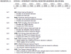
Another notable factor that contravenes with my understanding is a peripheral interrupt. What are the differences and similarities that exist between a peripheral interrupt and a global interrupt? As shown in the datasheet (depicted in the attachement).

Really, the only misunderstanding I have is those two facets. In algorithm form, I believe I'll first determine the INTCON settings, then IOC settings, and figure out some way to 'know' when an interrupt occurred in the main function. For instance,

Code:
        if(!GPIOX)     // Examine whatever pin you use?
        {
            Code;
        }

or

Code:
        if(GPIE)     // Use GPIO enable bit to examine status?
        {
            Code;
        }

Which one can I use? In the former arrangement, would I have to press the switch once to enable the interrupt and wake from sleep, then again to actually make it activate code?

I would appreciate any help!

Thanks,

Austin
 

Attachments

  • PIC12F629_INTCON_Register.PNG
    PIC12F629_INTCON_Register.PNG
    50.9 KB · Views: 420
You can do it in two ways.

1. Don't enable interrupts (GIE=0) and your code will continue after the sleep instruction when the switch is activated.
2. Enable interrupts (GIE=1) and your ISR will get executed when it wakes up. In this case a nop should follow the sleep instruction.

In both cases, before the sleep instruction you should enable and clear the IOC interrupt (GPIE=1, GPIF=0).

Note that during sleep no code is executed so it is impossible to poll your inputs.

The Global/peripheral interrupt difference is really just a legacy thing. The Peripheral ones just didn't fit in the original register and so new registers were added. So, Global are in INTCON and peripheral in PIR1 etc.

Mike.
 
Hi Pommie,

I appreciate your help tremendously!

I probably should explain my application better; you see, I'm not going to have any power switch on my mobile device (basically it's just a timer). Instead, I was going to have it sleep until a tactile switch is pressed and then commence timing. If I can't poll for when the switch was pressed, then I suppose it isn't possible for me to "know" when it is pressed while sleeping? Unless I'm mistaken, I thought this was what the interrupt on change (IOC) was for.

I would be grateful for any suggestions!
 
I think you are not understanding what sleep does. Sleep stops the oscillator and so no instructions are executed. The only things that can wake the chip are external interrupt sources, of which IOC is one, and reset or the WDT. When the chip wakes up you check which pin caused it to wakeup and take the appropriate action.

Mike.
 
Hi Pommie,

I read the DS of the PIC12F629, and Timer1 still runs while sleeping. As for the IOC, I suppose it wouldn't be any trouble to press the switch twice; once to effectively wake the µC, and then another time to take appropriate action. I know that switches often exhibit denouncing when pressed, so even if I press the switch once it might activate the timer anyway. How do I incorporate delay with my if statement? So for example, if GP0 is pressed for 100µS, then execute the following code.
 
Why do you think you will have to press the button twice? When the chip wakes up, you simply read the port to see which button was pressed. For a delay you just use the delay function supplied by HiTech, however, for debounce you probably want something like 10mS.

You are correct about timer1 but only if it is being clocked by an external signal.

Mike.
 
Hi Pommie,

I'm sorry! I'm still getting the hang of this concept, so I am very grateful to have your help.

I didn't realize that it was so simple! All I need then, is this, but with the SLEEP() command before:

Code:
if(!GPIOX)
{
     Commence Code;
}

I double-checked the datasheet and you are indeed correct about having only an external oscillator for Timer1 during sleep! Originally I was going to have the PIC sleep during it's timing periods, but now I realized that won't work. I'm trying to save as much power as possible, without adding extra components. Do you think I should just have my PIC burn up instruction cycles for delay, or is there another alternative solution that will use less power?
 
I think I would do,
Code:
    delay_ms(10);
    if(!GPIOX)
    {
         Commence Code;
    }

Just to eliminate bouncing.

Without knowing the application it's impossible to say what the best power saving method might be.

Mike.
 
Hi Pommie,

All I intend to do with this device is "time" 10 minutes as an "ON Cycle" and then time 30 minutes as an "OFF Cycle". So basically I'd have something like this as far as theory:

Code:
while(i<10min)
{
	Delay;
}

and

while(i<30min)
{
	Delay;
}

What I'm wondering is how I can reduce power consumption, if possible? Burning clock cycles in delay will require more power than sleeping, of course, but the point that I would need an external oscillator arises. If an oscillator would add $0.20-$0.60 to my expense I might comply with adding one. Also, I could pick a slow oscillator since it will only be timing.

I will run my device off of 2xAA battery cells so it might be possible to simply use the delay technique either with delay commands or with Timer1.

What do you think I should do?
 
As long as you can live with the 1% accuracy of the internal clock then I would try it and see. The standby current is around 700uA at 4MHz so 2xAA will last about 5 months. At 32k it is reduced to 18uA (will last a few years). Using a 32k crystal on Timer1 oscillator will allow you to sleep and consume around 7uA. If you switched to a 12f683 then you could use the 125kHz internal oscillator.

Best thing to do with something like this is to build it and see how it performs.

Mike.
 
Well the PIC12F683 looks perfect, and it's only just a little more in price! It seems that the internal oscillator can be selected to run at 31kHz (LFINTOSC), which would drastically reduce power consumption. I think I'll adjust the OSCCON register to 32kHz while timing and then change it to the default 4MHz while processing code.

Thanks for suggesting that PIC.
 
The reason I didn't mention the 32k clock was because it is extremely inaccurate and can be as much as 40% out. At 125kHz it will use about 300uA and so should last about 1 year. If you really need it lower then switch to a 32.768kHz crystal on timer1 and use sleep.

Mike.
 
Alright, I'll go ahead and use the 125kHz oscillator on the PIC12F683. I expect it to last more than a year since it spends most of it's time sleeping; waiting for the user to start the timer.
 
I'm performing some experiments on the PIC12F629, just to grasp an understanding of the concept. For some reason I can't wake up from SLEEP, does anyone see where the bug is?

Code:
//
//		SIOCSwitchTest1_12F629.C
//

#include <htc.h>
#include <pic12f6x.h>
#define _XTAL_FREQ 4000000

/***** CONFIGURATION *****/
// External reset, no code or data protect, No Brownout Detect,
// No watchdog, Power-Up Timer Enabled, 4MHz Int Clock
__CONFIG(MCLREN & UNPROTECT & BORDIS & WDTDIS & PWRTEN & INTIO);

void main(void)
{
	int i;
	TRISIO = 0x3D;
	CMCON = 0x07;
	GIE = 1;
	GPIE = 1;
	GPIF = 0;
	IOC3 = 1;
	
	while(1)
	{
		SLEEP();
		NOP();
		__delay_ms(10);
		if(!GPIO3)
		{
			GPIF = 0;	
			for(i=0;i<5;i++)
			{
				GPIO1 = 1;
				_delay(100000);
				GPIO1 = 0;
				_delay(100000);
			}
			while(1);
		}
	}
}

I am able to read from the port without the SLEEP command, so it must be something concerning my ISR?
 
Status
Not open for further replies.

Latest threads

New Articles From Microcontroller Tips

Back
Top