Continue to Site

Welcome to our site!

Electro Tech is an online community (with over 170,000 members) who enjoy talking about and building electronic circuits, projects and gadgets. To participate you need to register. Registration is free. Click here to register now.

  • Welcome to our site! Electro Tech is an online community (with over 170,000 members) who enjoy talking about and building electronic circuits, projects and gadgets. To participate you need to register. Registration is free. Click here to register now.

interfacing a CCS to a pic

Status
Not open for further replies.

MrDEB

Well-Known Member
looking at a method to connect a pic to these modules
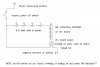
https://www.ledsupply.com/led-drivers/mean-well-ldd-l-series-cc-step-down-mode

project to have 10 channels per pcboard. The leds are these **broken link removed**

was looking at going with just mosfets to drive the led strings (6 leds per string at 24 volt battery supply) but led life expendency is ??
Originally looking at 4 leds in series and 12v supply
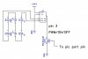
another idea was using the mosfts to drive the CCS modules. This may be the choice I should go with?? but seems like overkill??
Looked at using a TLC5917 8 channel CCS but only good for 120ma per channel
 
1) 12 or 24V batteries don't have 12 or 24V all the time. Charging will be 14.5 and 29V. When discharged the voltage might be 10 or 20V.
2) The module only reduces the voltage.
3) Don't know what color of LED but: 6 leds X 3.4V to 3.6V = 20.4 to 21.6V So the LED voltage will be in the 20.4 to 21.6V range.
3a) 4 LEDs and 12V supply will not work.
4) The module needs 3V to operate. (Vin=24, maximum Vout=21V) Note 4 page 1.

You need to think about the minimum and maximum numbers.
Battery could be has high as 29V and as low as 20V.
LED voltage could be 20.4 to 21.6V (6 LEDs)
Module will drop 3V at full on.

A PIC can drive the "on/off/PWM" pin to turn on/off/dim the LEDs.
 
I should have said more:
Battery could be down to 20V
Module drops 3V
Maximum total LED voltage is 17V.
If you has only 5 LEDs then 5x3.4=17V but 5x3.6=18V.

With 5 LEDs in a string you really need 21V of battery.
 
I called the company this morning and they suggested going with the 24 volt battery and 6 series leds.
The data sheet shows a pin on the module for ON/OFF so I am thinking of using the mosfets or similar to control the leds via a pic. the mosfets circuit I have uses logic level so it just might work(see attached for my original schematic). I tried contacting company to see what current draw the PWM/ ON/OFF pin # 3 requires but have to wait until Monday to get more info
 

Attachments

  • band schematic.jpg
    band schematic.jpg
    245.2 KB · Views: 314
Here is what I am considering depending on module requirements on pin 3 (PWM/ON/OFF
 

Attachments

  • band leds2.jpg
    band leds2.jpg
    174.7 KB · Views: 203
The on/off pin is designed to have a micro drive it directly. I don't think there will be a problem. Remove the MOSFET. It only pulls down. You need to pull up to above 2.5V or down below 0.4V
they suggested going with the 24 volt battery and 6 series leds.
I understand but do the math.
The example in the data sheet is using 6 3.0V LEDs.
6X3.0V=15
Plus the 3.0 loss in the module.
15+3=18V
Your LEDs could be 3.6V worse case.
6X3.6V=21.6+3V=24.6V
That probably will work with a 24V bench supply but not a battery.
 
Why not use a DC/DC step up and 12V and resistors? Then PWM the GND for brightness? Or am I being low tech/stupid?
 
I see what your saying and will think maybe add a voltage reg??
As for the led specs,
**broken link removed**
you guess is good as mine so planning on worse case.
Will confirm on Monday about pin 3
Led supply https://www.ledsupply.com has other drivers but cost is a factor ($4 vers $15
 
Why not just use a DC/DC converter? or connect them in parallel with a resistor on each? again simply PWM the GND for light control.

What you really need is a sphere magnet and microwave motor coil...... :D just kidding
 
looking over the data sheet and yes ron is correct as per data sheet that it appears the mosfets and related componets are not required but to play it safe I am emitting the mosfets and resistors and using ether a simple 2n2222 transistor or ??
the data sheet shows for control of the ON/OFF/PWM pin it requires
H>2.6-5.5vdc or open circuit
L<.4vdc or short
this is for the 1000-1500ma module
 
Since this is so far off the rails at the start, let me ask a really stupid question.

What are you planning to do with these LEDs? Have you given the slightest thought to the heat generated by a 3W LED? If not, once you get past the point of driving the modules (follow the advice of people who tell you "the micro pin will drive the PWM input directly") the LEDs will operate for about 30 seconds in open air at 3W before being destroyed.
 
the LEDs will operate for about 30 seconds in open air at 3W before being destroyed.
Spot the person who buys the posh Leds :D. Mine dont last that long :meh:
 
YES heat is a big factor so a heat sink is in the plan.
As for controlling the modules, I want some isolation between the pic port pins and the modules so looking at a 2n3904 transistor.
This will isolate the pic from the module and guarantee that the PWM/ON/OFF pin is either HIGH or LOW. May no be necessary but IMO a better mouse trap. Better safe than sorry. To play it safe, I plan to call the supplier on Monday to double check etc.
will post a schematic.
 
Spot the person who buys the posh Leds :D. Mine dont last that long :meh:

That was a guess ;) I still need to rework my magnifier lamp where I replaced the 10" round fluorescent tube with 16 1w LEDs on a aluminium circuit board. I didn't add any additional heatsinking to the ring inside the plastic housing. It started off gloriously bright but got dimmer and dimmer until one of the LEDs failed outright.
 
Little more math here then meets the the eye 4 leds is 12volts as posted i sim this for mrdeb it was funny but it shows a 1 amp drop which i would think 4 leds 4 amps but to ground its one amp from the leds and each led burns off a amp in heat i guess .
I was using 4 to test you use 4 amps from the supply and sink one amp at gnd.
There's a lot of heat

band-schematic-jpg.105638
 
Little more math here then meets the the eye 4 leds is 12volts as posted i sim this for mrdeb it was funny but it shows a 1 amp drop which i would think 4 leds 4 amps but to ground its one amp from the leds and each led burns off a amp in heat i guess .
I was using 4 to test you use 4 amps from the supply and sink one amp at gnd.
There's a lot of heat
I do not understand your words. Maybe my coffee is not working yet. lol
Heat comes form watts, which is Volts X Amps. 3 watts = 3 volts X 1 Amp
Motorcycle battery; voltage is 12V when the power is off. voltage = 14.5V (more or less) when the motor is on. I know that is picky but the current will be much more than 1A at 14.5 Volts. And much less at 11V. (using real LEDs and real batteries)

"it shows a 1 amp drop" "4 amps from the supply and sink one amp at gnd"
Current is much like flow of water. 1A comes from the supply and passes through D4, then D3, D2, D1 then into ground. The same 1A in all spots. (some people see current as negatives so current flows up or backwards)

Normally "12V" of LEDs should not be placed across a 12V source. LEDs need a resistor or some device to limit the current.
 
The other point I think worth noting, if you want isolation from the pic pin (needed IMHO), then surely a couple of opto isolators driving the transistors is the cheaper easier way and better. My own personal opinion is every Led has a resistor, maybe I am just unlucky but it never ends well for me any other way. Ok a current source is fine and that, but your having to rely on the LEDS being well matched.

I have thousands of Leds, I bet I cant find 2 very very closely matched though. So to me it seems pointless driving series strings from a fixed current source to the string. A resistor (1%) on each led is ideal, go small smd resistor if size is an issue.

Even the really tiny resistor are easy to solder, little tip...... Buy some Dow Corning high temp silicon grease as used in chemistry labs. On the tiny resistors you can put a tiny spot of the grease on the resistor between the pads. No way will you get a solder bridge. I use a cocktail stick normally to put it on. Or I do it directly on the PCB, but I get best results on the resistor.

Heat wise your asking for trouble not using current limiting for each Led, as the led heats the Vf changes. So if one Led is hotter than the others then it will not be matched so you start to see how things go the way of the pear.
 
The other point I think worth noting, if you want isolation from the pic pin (needed IMHO), then surely a couple of opto isolators driving the transistors is the cheaper easier way and better. My own personal opinion is every Led has a resistor, maybe I am just unlucky but it never ends well for me any other way. Ok a current source is fine and that, but your having to rely on the LEDS being well matched.

LEDs in series driven by a constant current source don't need to be well matched. The current through each LED will be exactly the same, regardless of Vf. The brightness may vary if they're not well matched. Power dissipation will vary too as Vf varies, but this shouldn't be an issue unless they are being driven at max power.

Opto-isolators are a good idea (provided they are placed in the right location) but you don't need an additional transistor to drive the module input pin that's designed to be driven by a microcontroller output. The output of the optoisolator is a transistor.

MrDEB hasn't said if he's planning to drive the modules with PWM to have brightness control. If that's his plan, I'm looking forward to seeing how he's going to drive ten(?) modules with a PIC18F-series.
 
ronsimpson
What I was saying is I played with the shc that Mrdeb sent me and these 3 watt leds get hot and need heat sink plus there not going to be happy with 12 volts. From a sim I ran on them. I would do them as most led lighting makers do you have sets of 3 with current resistors for each led
 
Status
Not open for further replies.

Latest threads

New Articles From Microcontroller Tips

Back
Top