Continue to Site

Welcome to our site!

Electro Tech is an online community (with over 170,000 members) who enjoy talking about and building electronic circuits, projects and gadgets. To participate you need to register. Registration is free. Click here to register now.

  • Welcome to our site! Electro Tech is an online community (with over 170,000 members) who enjoy talking about and building electronic circuits, projects and gadgets. To participate you need to register. Registration is free. Click here to register now.

Instrument Switching Pedal

Status
Not open for further replies.

captainate

Member
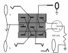
I decided to venture out and make my own switching pedal. Not too hard, right? With a good soldering ability but limited understanding of electronics, I was pleased to find this "schematic" (attached .pdf). However, once assembled and double-checked, it doesn't work! It is supposed to take one signal and divert them to one of two pathways, or take two separate instruments and use them with the following signal chain (I am using both Rhodes and guitar on stage, but never together).

So can someone help me identify the problem, and how to fix it? It seems like it should be a simple circuit for someone who knows what they're doing. Thanks,

Captainate
 

Attachments

  • AB_switcher.pdf
    537.2 KB · Views: 210
If you mixed up the x and y direction of the switch, that could account for the problem. Do you have a diagram of the switch contacts?
 
Another forum member already double-checked for me, I followed the schematic. I don't have anything other than what's already there, and pictures of my project below. I mentioned this problem in another thread, but since I started out with a relatively unrelated question, I figured a dedicated thread was necessary. The right channel (from below, same perspective as all pictures) does pass audio, although with severe ground loop hum. The left channel does not pass audio. Both LED's work correctly. Hope that helps,

IMG 1

IMG 2
 
With "just a glance", the cross connect is missing on the 3PDT switch. That X on the switch on the original .PDF is two separate wires. They seem to be missing. If this was a "reversing switch" for a DC motor, it would only go in one direction. Basically the same problem your having.

I spent about 10 seconds total time.
 
Last edited:
That "X" is there. The shielding on the wire I used was too big to fit through the contacts in the switch like the PDF. I just looped them around. I know I'm asking for a favor, but perhaps 10 seconds wasn't enough. I spent two hours.
 
I don't have the pics side by side. I haven't printed them.

It looks like your black wire to the mono phone jack is connected to sleave, but they are not connected to sleave of the stereo jack. Can you check that connection?


I'm not sure why a stereo jack is used because only two terminals are used on the jack.
 
Last edited:
So, basically the input is switched to one of two outputs and the LED is illuminated under the selected output? And probably the switch is an ON-OFF switch and not momentary.

Confusion is: Why is the input a stereo jack used?

Assume for the moment, that the input jack is supposed to be mono, but a stereo jack was used instead (hopefully I'm right).

A phone plug consists of SLEAVE, TIP and RING; A mono plug would have SLEAVE and TIP

Also look here: Tip and ring - Wikipedia, the free encyclopedia for a definition of TIP, RING and SLEAVE.

1) Make sure all of the SLEAVES are connected together of all three jacks (your black wire).

2) Insert a MONO plug into the stereo jack. TIP will be connected to a contact. Make sure there is a wire connected to this contact.

That picture is a "wiring diagram" and not a schematic. I personally find wiring diagrams more difficult, because you can't figure out the functionality.

I'm just having visualizing the metal contacts and the terminals because I'm deprived from all views.

Hopefully, I'm correct in the description of the operation and you can trace it out.
 
Last edited:
Yes, you are right about its functionality. I'm using it in the opposite direction, but I don't think that should be a problem. As an audio engineer (not an electrical engineer) I know all about tip, ring, and sleeve connectors, and have checked that all commons are connected on these jacks. The wiring diagram suggests the stereo jack is used for a battery powered pedal instead of DC. I didn't think about it before I ordered parts, and a mono jack would have worked just fine. But I did ensure that the connection between sleeves are intact. I even went further into the design of the pedal and it seems right to me. The design ensures that the tip and sleeve of the non-active output is grounded.
 
OK, I took a look at it as best as I could. I'm having trouble deceifering the stereo connections.

I believe you have hum: I don't know if I'm correct or not.

What I BELIEVE you have to do is: Switch the wires on the stereo jack and make sure the silver colored terminal is used which I think it is,

Don't call those pics a schematic. Call them a wiring diagram.
 
perhaps you have the witch wired 90 degrees off? there are 3 center contacts and 3 "normally open" and 3 "normally closed" contacts. in the original picture the 3 center contacts are the 3 contacts in the center row, going across horizontally. if you got the switch mounted with them going down the center column vertically, the switch won't work. you need to check with an ohmmeter to find out which way they go.
 
excuse the crude drawing, but i hope it's clear enough. i would use a 2 color LED, and a single resistor. one less hole to drill and one less resistor. note the sides of the switch where the case swage is on the sides. the DC source for the LED is 5 to 9V center positive.... most 2 color LEDs are center common cathode, you can use a red/green one if that's what you have. i just happen to have a lot of red/blue ones, and blue starts with B (helps keep things sorted out memory wise...) if you use a 9V source, change the resistor to 470 ohm.
 

Attachments

  • a-b-box.jpg
    a-b-box.jpg
    32.9 KB · Views: 166
Last edited:
a)what isn't functioning?
b)if you put one lead of an ohmmeter on the pin in the very center of the switch and test to the four of the pins around it (top being north, the one to the right being east, bottom south, left west) which direction shows continuity?
 
Status
Not open for further replies.

Latest threads

Back
Top