Electro Tech is an online community (with over 170,000 members) who enjoy talking about and building electronic circuits, projects and gadgets. To participate you need to register. Registration is free. Click here to register now.
Welcome to our site! Electro Tech is an online community (with over 170,000 members) who enjoy talking about and building electronic circuits, projects and gadgets. To participate you need to register. Registration is free. Click here to register now.
actually i dont have the circuit just now, but i got that circuit from electronics for you site, n if it is not correct then pls do sent me the proper circuit????????
pls help me out, it is quite necessary.
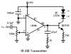
That is the Indian circuit that does not work:
1) The transistor is not biased so it rectifies the signal producing severe distortion.
2) The red LED abruptly limits the current which causes even more severe distortion.
I think the design of the IR receiver is just as bad.
Why not use a modern little power amplifier IC like an LM386?
It has much less distortion and uses much less battery current than the horrible old circuit.
It has a push-pull output that is capacitor-coupled to the headphones so they don't have DC in them.
The LM386 can have a gain of 200 if a capacitor is added from pin 1 to pin 8.
Hi Nice,
It is easy to use the LM386 audio amplifier IC to drive a power transistor that drives two IR LEDs in series with amplitude modulation. A 9V alkaline battery will become weak in about 10 hours.
India is on the other side of the world from me.
When I wake up in the morning it is very late at night in India but you are still awake.
Some TVs do not have an audio output. If yours does then try it.
Use an old cassette tape player.
Use a CD player or MP3 player to test your IR transmitter/receiver.
hello sir,
i have all the components with me, and i fabricated them on the bread board but i am not able to understand the connection of headphone on the breadboard.pls help me?????
n someone suggested me to use a mic as input, would it be correct to use a microphone????????
This site uses cookies to help personalise content, tailor your experience and to keep you logged in if you register.
By continuing to use this site, you are consenting to our use of cookies.


") Mic's maybe.
Mic's maybe.