Continue to Site

Welcome to our site!

Electro Tech is an online community (with over 170,000 members) who enjoy talking about and building electronic circuits, projects and gadgets. To participate you need to register. Registration is free. Click here to register now.

  • Welcome to our site! Electro Tech is an online community (with over 170,000 members) who enjoy talking about and building electronic circuits, projects and gadgets. To participate you need to register. Registration is free. Click here to register now.

infrared cordless headphone

Status
Not open for further replies.
hello sir,
i have all the components with me, and i fabricated them on the bread board but i am not able to understand the connection of headphone on the breadboard.pls help me?????
The headphone in my receiver circuit connects from the negative wire of the 470uF output coupling capacitor to 0V. If the headphone is made for two ears and each is 32 ohms or more then connect them in parallel. If they are each 8 ohms then connect them in series but with the correct phase.

someone suggested me to use a mike as input, would it be correct to use a mike????????
Mike is too far away for you to use him and you are too young for him.
Use an electret microphone instead.

Adding a 10uF capacitor from pin 1 to pin 8 of the LM386 boosts its gain 10 times to 200. Then an electret mic can be powered and connected to the input volume control like this:
 

Attachments

  • IR AM transmitter with mic.PNG
    IR AM transmitter with mic.PNG
    15 KB · Views: 207
i also meant to say a microphone, it was just a spelling mistake..
We hope you don't mind that we are teasing you.
1) Because you are a girl.
2) Because you are young.
3) Because you might be nice.
 
A film capacitor is sometimes called a mylar capacitor. In the orient they use "green caps" that are green but I have seen dark reddish-brown ones.
220nF would be marked 224.

There are good girls and there are nice girls. Never mind, you are too young.
 

Attachments

  • green cap.PNG
    green cap.PNG
    20.1 KB · Views: 203
  • Epcos capacitors.jpg
    Epcos capacitors.jpg
    9.9 KB · Views: 191
pls tell me what is the range for this circuit, since the ir leds that i used can work only upto 3 inch, how to increase the range????????
 
pls tell me what is the range for this circuit, since the ir leds that i used can work only upto 3 inch, how to increase the range????????
It should be much farther.
1) With the transmitter powered from a 9V battery for a few minutes, measure the voltage across the battery and across the 120 ohm resistor.
2) Turn up the volume on the receiver then turn up the volume on the transmitter until the sound is distorted.
3) Try it in a dark room.
4) With the receiver powered from a 9V battery for a few minutes, measure the voltage across the battery and across the photo-transistor with and without it exposed to IR from the transmitter.

What are the part numbers or please post the datasheets of the IR LEDs and of the photo-transistor?
 
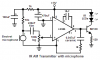
see, i simplified the circuit through help of one of my senior, and it is working, but still the range is very less, what to do ?????????

the two op amps used in transmitter and reciever are lm358.
and datasheet for led is not available at the shop, shopkeeper doesnt know about its specification.....

will the range increase if i would use one or more IR LEDs??????
 

Attachments

  • transmit.doc
    69.5 KB · Views: 226
Last edited:
Sorry, but there's very little 'right' about either of those circuits.

First off, no decoupling capacitors anywhere, and both opamps are been run with an input impedance of only 1K, far too low for either transmitter or receiver.
 
the opamp for the transmitter has a signal voltage loss of much more than 100 times instead of a signal voltage gain.
The feedback pot is only 100 ohms maximum. an opamp can barely drive 1k ohms, not 100 ohms and less.
The 1k input resistor is like a short to ground to the microphone.

A mic preamp for an electret mic is supposed to have a gain of about 100 (not a loss) and have an input impedance of about 47k ohms, not 1k.
So the preamp opamp should be non-inverting to have a high input impedance and have a voltage gain.
 
Thanks audioguru

Hi Nice,
It is easy to use the LM386 audio amplifier IC to drive a power transistor that drives two IR LEDs in series with amplitude modulation. A 9V alkaline battery will become weak in about 10 hours.

What country are you in?

dear thanks a lot for ur this help i am also searching for a circuit and here i got it thanks alotttttttttttttt
 
hiii i'm new to these forum please tell me how to increase the range of infrared cordless headphone
i have done the project using ur circuit it is working but the range is only 1 metre how can i increase the range to atleast 4 metres
 
hiii i'm new to these forum please tell me how to increase the range of infrared cordless headphone
i have done the project using ur circuit it is working but the range is only 1 metre how can i increase the range to atleast 4 metres
If you made the circuits that use an LM386 amplifier IC in the transmitter and receiver then the range can be increased by adding more BD139 transistors with IR LEDs and 120 ohm resistors. Also the range can be increased by adding a preamp transistor to the input of the LM386 IC in the receiver.
Since it uses IR then the range is farther in the dark.
 
Status
Not open for further replies.

Latest threads

Back
Top