Electro Tech is an online community (with over 170,000 members) who enjoy talking about and building electronic circuits, projects and gadgets. To participate you need to register. Registration is free. Click here to register now.
Welcome to our site! Electro Tech is an online community (with over 170,000 members) who enjoy talking about and building electronic circuits, projects and gadgets. To participate you need to register. Registration is free. Click here to register now.
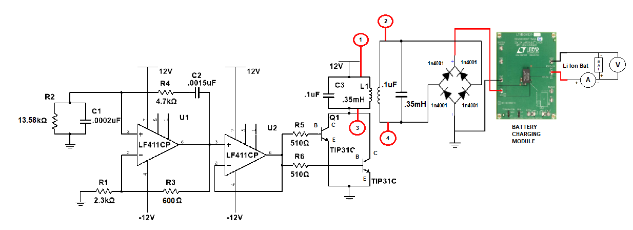
Regarding the figure below, what is the proper way to measure the Voltage across the inductor? although it is not a good idea that I used class c amplifier.
I assume you mean across the L1 transformer primary.
If the power supply outputs are isolated, then connect the oscilloscope common to the +12V supply to measure from point 1 to 3.
(not isolated in #2)
Connect the scope ground to your ground. Connect the probe to (1) which is 12V. Set the scope to display this in the center of the picture.
Now move the scope probe to (3) and you should see a picture where 0 volts across the transformer is the center of the picture.
Another way: We know there can not be DC across a coil or transformer. Set the scope to "AC" and the scope will remove the 12V DC from the picture.
what is the theory behind why there is a DC component receiver coil? when the transmitter transmits AC signal with DC component does is it also receive ac signal with dc component?
This site uses cookies to help personalise content, tailor your experience and to keep you logged in if you register.
By continuing to use this site, you are consenting to our use of cookies.