Continue to Site

Welcome to our site!

Electro Tech is an online community (with over 170,000 members) who enjoy talking about and building electronic circuits, projects and gadgets. To participate you need to register. Registration is free. Click here to register now.

  • Welcome to our site! Electro Tech is an online community (with over 170,000 members) who enjoy talking about and building electronic circuits, projects and gadgets. To participate you need to register. Registration is free. Click here to register now.

Inductive load

Status
Not open for further replies.

geochurchi

New Member
Hi All, we are trying to power some restored RR crossing bells from a 12 VDC power supply and the power supply burned out, I doubt it was due to the load, some suggested that we can’t do that with an inductive load, any thoughts?
Geo
 

Attachments

  • D60CEB35-73E0-4422-A26F-A9AAE0106A2C.jpeg
    D60CEB35-73E0-4422-A26F-A9AAE0106A2C.jpeg
    2.8 MB · Views: 207
  • E00C9F60-5477-4312-91E7-7AEC8BA10908.jpeg
    E00C9F60-5477-4312-91E7-7AEC8BA10908.jpeg
    1.3 MB · Views: 200
I think there is not a problem with inductance in the load. The Bell probably pulls too much power.
 
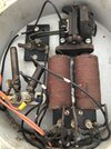
12 V across 10 ohms is only 1.2 A. A more likely cause is the back EMF spike when the contacts open. There is an R-C snubber in there, but this thing was designed way before switching or other regulated supplies. A fast diode directly across the coils, like a Shottkey or a tranzorb, would be better protection. However, this now makes the device polarity-sensitive. Placing the diode across the power supply output still lets the spark happen across the timer contacts, but should be enough protection and it doesn't force polarity sensitivity onto the device.

ak
 
Do you have access to a multimeter? If so, can you measure it's resistance?

Mike.
 
Status
Not open for further replies.

Latest threads

New Articles From Microcontroller Tips

Back
Top