Continue to Site

Welcome to our site!

Electro Tech is an online community (with over 170,000 members) who enjoy talking about and building electronic circuits, projects and gadgets. To participate you need to register. Registration is free. Click here to register now.

  • Welcome to our site! Electro Tech is an online community (with over 170,000 members) who enjoy talking about and building electronic circuits, projects and gadgets. To participate you need to register. Registration is free. Click here to register now.

In-circuit PIC Problem

Status
Not open for further replies.

Andrei_D12

Active Member
Hi!
I started this topic because I want to discuss a problem related to PIC controllers (12f629 and 16f628A). I will try to give you all the details of this.

The problem is: after succesfully compiling the code and burning it in the PIC's memory, when I put the controller in the circuit... nothing happens!!!

Initially I thought that the problem is in my code. I corrected all my mistakes from the .asm document then placed again into device. The problem persisted.
Then I checked all the connections in my circuit. The controller has a 100n decouplling capacitor across it's power pins, 3-4v supply voltage (3.7v from a lithium battery) and the circuit is built on breadboard. After carefully checking the connections, I turned on the circuit. No result!
Perhaps the device was faulty. I tried all my 5 12F629 pieces and... nothing. The same phenomenon happens when using 16F628A (which surprised me because most of my PIC projects were using this device and worked perfectly in the same conditions!)
When I am experimenting with controllers, I use MPLAB IDE 8.92. I create a project (by using Project Wizard), select the device, then add a template file and a linker file, create the project and build it... All works perfect. I write my code, then connect the PICKit2 clone. The computer connects to the hardware. I connect the PIC to the programmer and it shows the messgage "PIC**F62** found". I burn the code and MPLAB confirms that the code has been succesfully burned. I turn the Vdd off from software and extract the PIC, then place it in my circuit.
This is the way I build projects. Dozens of simple projects worked very well until this problem occured.
I am still a beginner in programming MCUs, and had some problems which I finally solved and understood their causes, but this problem... I just cant't solve.
It may be an obvious error that causes this (and I haven't noticed it yet) or it may be a complex error which requires thinking and analysing.

This is why I believe that the point of view of another person will make a difference.

Any word of advice will be highly appreciated!
Thank you!
 
PORT set up for analog (default state) instead of digital ?

JimB
 
Bad/missing connection on the breadboard?
 
Include a simple "light a LED" with a spare port pin to see if the code is running.
Max.
 
My 2 cents / pence , perhaps an un-coded interrupt , watch dog timer caught me out once ... Max's LED is a good idea.
I prefer to do ICSP , worth a few extra components and or jumpers .
 
Without code and schematic, no-one can advise... Most of these issues are to do with MCLRE and or LVP...
This is a problem that occurs at all my projects now, no matter it is simple or complex.
Bad/missing connection on the breadboard?
I have checked this and the connection wasn't faulty. I have placed the circuit in other spots on the breadboard, spots that I have used rarely.
Include a simple "light a LED" with a spare port pin to see if the code is running.
Max.
To covince myself that the code was the problem I burnt a flashing led program written by another programmer. Again, no result.
PORT set up for analog (default state) instead of digital ?

JimB
I have disabled all the extra functions to ensure that I could use the I/O pins.
My 2 cents / pence , perhaps an un-coded interrupt , watch dog timer caught me out once ... Max's LED is a good idea.
I prefer to do ICSP , worth a few extra components and or jumpers .
I haven't done this before. I will try this...
 
This is a problem that occurs at all my projects now, no matter it is simple or complex.
This would suggest something complex or stupid... but thats not much help , possible power problems ? stray capacitance, programmer has toooooo long wires ...
 
What oscillator type have you configured. There would be MUCH more cance of getting help if you would supply a schemaitic and the code of one of the devices that does not work. I have never had any problem getting a PIC12F629 to work.

Les.
 
This can be just about anything - bad power, PIC not running at all, pins misconfigured. Imagine your car doesn't start. You wouldn't expect that this in itself is enough information for a mechanic who's 3000 miles away tell why your car doesn't start.

Start from something really small, like measuring supply voltage and then move on by very little steps. If you want others to look at this, post schematics, pictures etc.
 
In the past I was dealing with the following problem. The device wasn't recognised by the programmer. "Unexpected id, expected 0xbe, read 0xf" or something
What oscillator type have you configured. There would be MUCH more cance of getting help if you would supply a schemaitic and the code of one of the devices that does not work. I have never had any problem getting a PIC12F629 to work.

Les.
I am using the internal 4 MHz oscillator on 16f628A and 12f629.
I will place a program for 16f628a.
This is a program written by me.
It flashes 3leds on RB 0,1,2.
 

Attachments

  • 16F628ATMPO.ASM
    3.6 KB · Views: 272
Last edited:
I have used the same templates and procedures (and hardware). Configure the inputs/outputs, deactivate the unused comparators and others.
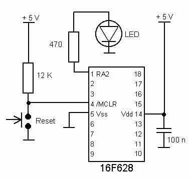
628led.gif

This is my first project using 16f628a (a led flasher) and the program is written by another programmer. The program in this case is here. I was amazed by the fact that the led didn't flash this time.

I wanted to see the points of view of someone with more experience. Now I have more ideas when it comes to investigating the problem and I am sure I will finally solve this problem. Thank you for all the help!!! :)
 

Attachments

  • 628LED.asm
    2.1 KB · Views: 285
Just a observation... You mentioned a voltage supply of 3~4v using a lithium 3.7v battery..
I know the BOREN is off but I distinctly remember something about "couldn't go below 4.2v" on an F type chip.. I had to replace it with the LF version to run at 3 volts... Maybe something I did wrong..

Also note that the pic12f629 has that awfull osccal value and BandGap figures that need to be saved before re-programming!!

However!! Your schematic shows 5v so maybe its not your issue...
I read something on the internet about that OSCCAL value which can create problems. What's trully weird is the fact that when I first burned a 3 led flasher in the 12f629 IT WORKED just as intended. But after a few experiments something didn't go well. I have 5 pieces of 12f629 and since the first one "refused" to work, the others behave the same. 16f628a continued to work fine until it started to create the same problems. I know its a weird phenomenon (that's why i haven't included a schematic) because it happens on all my MCUs. As for the supply voltage, I have used 3 volts in many cases and no problem occured.
Perhaps I should configure the 12f629 to use a RC oscillator since my projects don't need an accurate timing.
 
I read something on the internet about that OSCCAL value which can create problems.
If you've done a bulk erase of the chip and erased the OSCCAL data by mistake then yes, you could well have problems.
 
Andrei,

You say you have used the same hardware already but I would follow the circuit in the datasheet (fig 14-11 IIRC) to reset the /MCLR pin. In my case I also use that button to avoid cycling power.
 
Hi Andrei,
I've just built the circuit in post #13 and programmed the PIC with 628LED.hex. I assembled it using MPASM V5.55 then programmed a PIC16F628A ( I erased it first as I did not know what I used it for last. ) with the HEX file using a home built PICKIT2 clone. It worked without even without pressing the reset button.

Les.
 
Status
Not open for further replies.

Latest threads

New Articles From Microcontroller Tips

Back
Top