Continue to Site

Welcome to our site!

Electro Tech is an online community (with over 170,000 members) who enjoy talking about and building electronic circuits, projects and gadgets. To participate you need to register. Registration is free. Click here to register now.

  • Welcome to our site! Electro Tech is an online community (with over 170,000 members) who enjoy talking about and building electronic circuits, projects and gadgets. To participate you need to register. Registration is free. Click here to register now.

Implement PFC controller properly to AC/DC converter

Status
Not open for further replies.

mading2018

Member
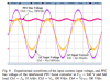
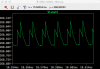
I am trying to implement a PFC controller to AC/DC converter stage, but I have some problems to get the current feedback correctly so the output is more steady state. Also, the waveform have transients in the beginning, it is possible to reduce these transients?

I have connected a transistor in parallel to the load at the output, just to simulate the switching frequency from the DC/DC converter stage, which is in the next stage.

I have attached two files here (one with LT8312 and another with LT1249 PFC), so you can try them.

All help is appreciated it, thank you.
 

Attachments

  • AC-DC with PFC_LT8312.asc
    8.9 KB · Views: 210
  • AC-DC with PFC_LT1249.asc
    5.3 KB · Views: 207
so the output is more steady state. Also, the waveform have transients in the beginning, it is possible to reduce these transients?
The PFC circuit is not made to give good power. All PFC circuits I know of have transients and ripple. This is the way they are. The job of PFC is to get power off the power line in a good way. After the PFC where should be another PWM to make good power.

I looked at your 1249 circuit only.

I have connected a transistor in parallel to the load at the output, just to simulate the switching frequency from the DC/DC converter stage, which is in the next stage.
The transistor is not connected right. (source is not connected) This is good because the transistor would short out the load.
 
Okay, so what I understand, the other PWM that will fix the transients is coming from the DC/DC converter stage?
Can you please connect these two converters together? Apparently I seems to do something wrong when connecting these two converters. I know the DC/DC converter stage works properly.

Thank you
 

Attachments

  • AC-DC with PFC_LT1249.asc
    5.4 KB · Views: 224
  • DC_DC Converter FUNKAR 320V+Battery.asc
    4.7 KB · Views: 216
Last edited:
The PFC circuit is not made to give good power. All PFC circuits I know of have transients and ripple. This is the way they are. The job of PFC is to get power off the power line in a good way. After the PFC where should be another PWM to make good power.

I looked at your 1249 circuit only.

The transistor is not connected right. (source is not connected) This is good because the transistor would short out the load.

Please, Ron, if you have time. Could you please trying to get these circuits working properly together? I know now that the battery model is designed wrong so I need to change that, and some parameters.

Thank you
 
The PFC circuit is not made to give good power. All PFC circuits I know of have transients and ripple. This is the way they are. The job of PFC is to get power off the power line in a good way. After the PFC where should be another PWM to make good power.

I looked at your 1249 circuit only.


The transistor is not connected right. (source is not connected) This is good because the transistor would short out the load.

So you would say the circuit (LT1249) works quite properly?
 
Thats great! However, I hope it is okay if can ask a question regarding the AC/DC Converter with interleaved PFC again. I am trying to simulate that circuit, but what I have understand I need to implement an IC circuit of the interleaved PFC, in order to simulate an interleaved PFC.

Since it is complex, is it possible to only use voltage sources as pulses instead to simulate an interleaved PFC? I have attached my attempt to do it.

I did implement an EMI-filter after the AC input, but I am not sure how it should look like? Is it a standard EMI filter consisting of 2 inductors, and 4 capacitors? I am not sure, cause some sources says it is including more or less than that. I have done that for my DC/DC converter, see the second attached file. I think it still giving constant output voltage after some time, so thats good I guess.
 

Attachments

  • OBC_ACDC_16A.asc
    5 KB · Views: 212
  • OBC_DCDC.asc
    5 KB · Views: 208
Last edited:
The filter inductors are wound on the same core like a transformer. "K1, L3 L4......"
100uf on the power line is too much.
I don't know where you will find a spice for a PFC IC that is interleaved.
 

Attachments

  • PFC INT.ASC
    5.1 KB · Views: 210
I see. But I think it is possible to use the voltage sources (since the current and voltage are already in phase with each other) connected to the MOSFETs, so it should be okay.
Like before, do you have some suggestion how I can improve PFC (output voltage) from the converter. I asking, cause I am not sure if the voltage looks so similar to the research paper.
But maybe it is a ripple I notice. In the paper they got 300 V as output and I got 270 V. So I think this could be correct.

The main idea is to get this to circuit work properly for 16 A, than I will trying to have other input currents (lower currents, 2, 4, 6, 8 A) to see what happens.
 

Attachments

  • pfc voltage comparssion.png
    pfc voltage comparssion.png
    96.4 KB · Views: 235
  • PFC voltage.png
    PFC voltage.png
    51.7 KB · Views: 224
Last edited:
This picture is the ripple at the switching frequency. Over 100uS.
upload_2018-3-21_7-51-19.png

This picture is much much more time. This is the 50/60hz from the power line.
upload_2018-3-21_7-52-42.png

The top picture is a very very small spot in the red trace.
 
Yes, I just notice that. Thank you. So I guess the circuit works quite good. It works actually better without the EMI filter, so I will neglect them I think.
I am not sure tough why the output voltage (PFC bus) is increasing, it should be constant at one point I assume, but maybe I am wrong.
 

Attachments

  • forum ron.png
    forum ron.png
    27.8 KB · Views: 222
I do not know what your circuit is doing. Do you have a error amp that watches the output voltage?
 
No, I do not have that. But I am not sure how to implement it in LTspice, I tried that before, but I could not get it to work. Do you have an example how it could look like for my circuit?
 
Status
Not open for further replies.

Latest threads

New Articles From Microcontroller Tips

Back
Top