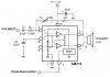
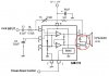
Up late, Mike? Seems to be building an acoustic coupled dialer. It works, but only with a large speaker which happens to be 8 ohms. He wants to make it work with the tiny 18mm speaker which happens to be 150 ohms.
But the 18mm speaker has a gross peak between 1kHz and 1.8kHz that violates the phone co's sense of what dtmf should sound like. I'm hoping that a lpf with 3db point around 1k won't be too lossy and still tame the peaking.

")