Continue to Site

Welcome to our site!

Electro Tech is an online community (with over 170,000 members) who enjoy talking about and building electronic circuits, projects and gadgets. To participate you need to register. Registration is free. Click here to register now.

  • Welcome to our site! Electro Tech is an online community (with over 170,000 members) who enjoy talking about and building electronic circuits, projects and gadgets. To participate you need to register. Registration is free. Click here to register now.

Identify a circuit.

Status
Not open for further replies.

Lightium

Active Member
I've read that this is a multivibrator circuit, but how is it a multivibrator and what kind?
 

Attachments

  • Screenshot at 2022-06-26 14-41-20.png
    Screenshot at 2022-06-26 14-41-20.png
    43.4 KB · Views: 177
It looks to be a schmitt trigger type oscillator.

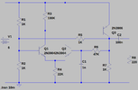
A similar concept to this one, where the input threshold is changed as the output switches high or low, and the capacitor has to charge or discharge past that threshold point each way for the output to switch to the opposite state.

220px-OpAmpHystereticOscillator.svg.png
 
The circuit can be viewed as a very crude op-amp variant. I borrowed both images just to give an idea how or why it can be viewed as an opamp.
 

Attachments

  • elektrisk-krets-opamp.png
    elektrisk-krets-opamp.png
    127.4 KB · Views: 162
Grossel, should I be getting a square wave or sine wave on R8?
I'd expect neither. Unfortunately I don't happens to have a simulator software installed, but somebody else in here probably has, to provide an exact answer. Schmitt trigger, of course it should be expected square wave :oops:
 
Last edited:
Some months ago, I had the task of analysing this circuit:
1656368975655.png

As you can see it is a very close relation to the circuit in post #2.

It is a slow oscillator producing short pulses of 0.6s duration, every 5.8s.
This asymmetric waveform is due to D1 and R3 in parallel with R4.

I expect the waveform of the circuit in post #2 to have a 50/50 mark space ratio.


Here are the waveforms at the op-amp inputs, the output of the op-amp is a square wave.

1656369116413.png


1656369273935.png


1656369856750.png


Enjoy.

JimB
 
Status
Not open for further replies.

Latest threads

New Articles From Microcontroller Tips

Back
Top