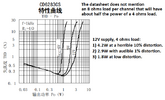
Hello, i have a problem while making this circuit. When the volume is above 50% the bass and the entire sound is getting distorted too much. And after 2-3 days right channel got lower audio output than the left channel. I used new components and checked the polarity and connections more than 5 times.
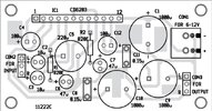
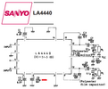
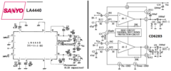
Can any of you please provide a better circuit schematic for the ic 4440?
I'm using two 8 ohm box, inside each boxes there are two 8ohm speakers (tweeter and woofer) connected in a parallel crossover with low pass and High pass coils.
Can any of you please provide a better circuit schematic for the ic 4440?
I'm using two 8 ohm box, inside each boxes there are two 8ohm speakers (tweeter and woofer) connected in a parallel crossover with low pass and High pass coils.