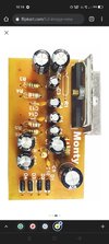
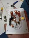
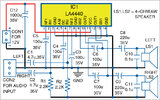
I think i said it wrong, this is how it's connected (not 4700uf its 2200uf)
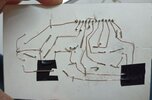
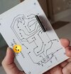
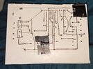
Have a look at this, both (c13, c14) ceramic caps bellow the 1uf electrolyte are 102, if i replace them using 103 would that be a huge problem? The 102 isn't available in the market near me.ALL the electronics You tube videos are made by people on the other side of the world who carry the solder on the dirty tip of their soldering iron. The amplifier videos all show small speakers with no enclosures playing no low frequencies. A few of the videos show a little 9V battery.
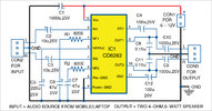
Did you notice that the LA4440 and CD6283 look the same but their pin numbers are different?