Continue to Site

Welcome to our site!

Electro Tech is an online community (with over 170,000 members) who enjoy talking about and building electronic circuits, projects and gadgets. To participate you need to register. Registration is free. Click here to register now.

  • Welcome to our site! Electro Tech is an online community (with over 170,000 members) who enjoy talking about and building electronic circuits, projects and gadgets. To participate you need to register. Registration is free. Click here to register now.

I want to connect a Peltier Element to a 3.3V power supply

Status
Not open for further replies.

daniela18

New Member
Hi,
I need help to anyone who can help me :)

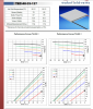
I want to connect a Peltier Element to a 3.3V power supply . I use TEC-40-33-127.
I attached below some specifications of the device.

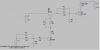
I need your help because I don't know how to make the circuit schematic I don't know what values to choose from resistors, capacitors and what kind of transients to use, how to amplify and to maintain the current, voltage so as to the whole circuit should work .

Thank you! :D :)
 

Attachments

  • peltier.PNG
    peltier.PNG
    207.2 KB · Views: 286
4.3 amps at 15v is a big ask? And that will be the minimum… 21 amps from a 3.3v supply! Can your supply deliver 21 amps? As you probably know, you can't amplify watts.

If your supply can't supply 72 watts, you wont ever get 72 watts...
 
Do the maths - as Eric says you need 72w, neither the battery or the module (coincidentally I'm fitting 20 of those exact modules at this very moment!) will provide anywhere near 72w.
 
Do the maths - as Eric says you need 72w, neither the battery or the module (coincidentally I'm fitting 20 of those exact modules at this very moment!) will provide anywhere near 72w.
What do the different colors in the lower two graphs means?
I guess OP could run the peltiers underpowered, but there will not be as big delta T as when run at full power.
 
What do the different colors in the lower two graphs means?
I guess OP could run the peltiers underpowered, but there will not be as big delta T as when run at full power.
Two AAA batteries wouldn't last long?? Not much heat?
 
None of the figures make any sense. The module has a DC resistance of approx 1½Ω - apply 3V to this and 2A will flow. Your 2A stepup module will have to be swapped for a step down module. I've used these devices and you need a 200W 12V power supply to get any reliable results.

Mike.
 
None of the figures make any sense. The module has a DC resistance of approx 1½Ω - apply 3V to this and 2A will flow. Your 2A stepup module will have to be swapped for a step down module. I've used these devices and you need a 200W 12V power supply to get any reliable results.

Mike.

I can't help but think, every time someone asks about Peltiers here, they always seem to have no understanding of them, and completely unrealistic expectations.
 
I think that she can "underpower" the peltier and I am wondering if that is not part of the assignment challenge. If you read the OP's first post here, you can see that there are some specific design elements as I would expect in an assignment.

As I understand it, the Qmax values do not have to be met, see here and the graphs in the data sheet, to get the unit to drive some temperature differential. I am begining to think that the component list (from the first post), including the MT3608 , is part of the assignment and that is why I asked about the chamber dimensions and target temperature changes and so on. My query has not been addressed yet, but at some point, I think that this will become clearer.
 
None of it makes sense. The OP needs to give us more information or accept that 3.3V is doing nothing on a peltier device.

Mike.
 
None of it makes sense. The OP needs to give us more information or accept that 3.3V is doing nothing on a peltier device.

Mike.

Yeah, well, that is a little bit how I felt when I read the first post in the first thread. So I asked the questions, but here is the next thread with no response to the first thread questions.

Very different situations If, on the one hand, you were given a list of component that had to be used to build a project that would do a specific something, versus, I want to power this peltier with this power supply and step up. Not to even mention the "homework" aspect.

You get better help if you provide more information about the what and why....but that is not news, eh?
 
I have watched several youtube video's where they are using Peltier devices to cool rooms.

Using the same device and 9v 500mA , Not so good!! 5v 3A was satisfactory... 12v 4A was excellent...

There are many video's showing cooling ad heating with these devices... BUT!! one thing they all have in common HUGE heatsink and fan...
 
I want to control the element using a launchpad. I want something similar as in the schematic.
 

Attachments

  • schematic.PNG
    schematic.PNG
    34.4 KB · Views: 263
What is the purpose of the capacitors and voltage dividers in your circuit?
 
Use a low turn on voltage MOSFET.
MCH6448 Might work. or IRF7601T
You will need a part that turns on well at 3 volts. (not "just on" at 3V)
 
IRF7601 MOSFET
How to choose a MOSFET for low gate turn on voltage. (drive the Gate of a MOSFET directly from a u-computer)
This graph shows current on the left side. Voltage across the Drain-Source on the bottom. Each line is for a different Gate-Source voltage.
If you applied 1.5V to the gate the MOSFET will "turn on" for low currents like 100mA but at about 150mA it tears open. (D-S voltage goes up)
AT 2.0V Gate voltage the part can control 3A.
I think your computer outputs 3 volts. At 3V G-S voltage the part can control about 20A.
120082

If you are controlling 10A with a G-S voltage of 3.0V the D-S voltage will be about 0.4V. (0.4V X 10A = 4watts) So the part will heat up with 4 watts.
Also know this graph is for room temperature. As the part heats up it is not this good. There is another graph for a hot part.
This part says in words that it will turn on at 0.7V (@ 250uA). That current is next to nothing. You need to look at the graphs to know how it will function at your current and gate voltage.
 
If I may I'm going to refer to you as "spot on Ron" in the future.

Cause you know stuff and never guess.
Just reliable info is what you do :)
 
something similar as in the schematic.
This will turn on/off slower. You have no reason to turn the Peltier on/off at 100,000 times/second. This will work at 50hz or DC.
120083

The IRF1405 is very large. It needs a good 5V or more on the gate.
 
Status
Not open for further replies.

Latest threads

New Articles From Microcontroller Tips

Back
Top