Continue to Site

Welcome to our site!

Electro Tech is an online community (with over 170,000 members) who enjoy talking about and building electronic circuits, projects and gadgets. To participate you need to register. Registration is free. Click here to register now.

  • Welcome to our site! Electro Tech is an online community (with over 170,000 members) who enjoy talking about and building electronic circuits, projects and gadgets. To participate you need to register. Registration is free. Click here to register now.

I need a relay.

Status
Not open for further replies.
What do you think ?

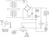
After figuring my LED in the previous circuit I got some 1.2k 1/2 watts. I put three in series rendering 3.5k - 1.5 watts. I'm not sure about that yet but.....

I measured 37.4.v across the cap and with the coil in circuit across the coil was 36.5v.

So, I put in the LED measuring the vf at 1.9 which should give me about 10ma operating current.

Edit: I might add it took a bad Hum out of the Transformer also.:)


kv
 
Last edited:
Update.

Update, I began to build and pair boards to transformers.

One of them was really crummy the Volt Meter measured almost 48v and it took out my led.

I'm trashing it or taking it back hoping they will replace it but, the .5a are the ones with the problem the 1a is doing alot better with everything in circuit about 36v while the others are around 42-48v. I think I'll try getting more of the 1amps.

In addition they only had some metal oxide 3k9 in stock. Wtih it in circuit it with the hooked up to the bad transformer it smoked a little. So, I took it out and put in my left over 1k2's carbon film I'm just going to run them in series.


kv
 
Last edited:
My Boss is nervous

Eric, What kind of safety can I put on this circuit.

Maybe a zener and fuse or something. If so, where and how would be best ?


kv :)
 
Eric, What kind of safety can I put on this circuit.

Maybe a zener and fuse or something. If so, where and how would be best ?


kv :)

hi kv,
It would be advisable to fit a fuse/s in parts of the circuit.

Can you post your final circuit, so that we look see.??
 
New Transformers better.

hi kv,
It would be advisable to fit a fuse/s in parts of the circuit.

Can you post your final circuit, so that we look see.??

Soon as I can. Along with my regular duty's.

I've built the first 2 boards. I still need to run wire in the other room. I'll be adding more 5v relay's then run the central ground for the (Pb's) on the N.C. side of the relay in order to (lock out) other user's in the room preventing them from turning off a mic's while in use.

I just received my 50 mm Led I can make either red,green,yellow which uses a 120vac source.

Then they had one that is 18v to 30vdc and has four colors I'm told it is brighter. I need to see the difference in luminance.


Thanks Eric.


kv
 
hi,
Look over this circuit.:)

https://www.electro-tech-online.com/attachments/kvrelay1-gif.26260/


I want to replace the relay with my 50mm led light ?

The 50mm Led light consist of about 8 smaller Led in parallel the manufacturers voltage to drive them is 18v to 30v.

If I check it out of circuit the 2 leads (+-) I'm getting about 1.927 on my meter. So, I think LED's are in parallel + 420ohm on each one. Anyways.

12-0-12 transformer. Without the smoothing capacitor it's about 32v with capacitor in jumps to 38v would I be safe to put the light in circuit.

kv
 
Last edited by a moderator:
kvrelay1-gif.26260


I want to replace the relay with my 50mm led light ?

The 50mm Led light consist of about 8 smaller Led in parallel the manufacturers voltage to drive them is 18v to 30v.

If I check it out of circuit the 2 leads (+-) I'm getting about 1.927 on my meter. So, I think LED's are in parallel + 420ohm on each one. Anyways.

12-0-12 transformer. Without the smoothing capacitor it's about 32v with capacitor in jumps to 38v would I be safe to put the light in circuit.

kv

hi,
If you have a 420R in series with each 2V led, then at 18V thats 38mA/led
at 30V thats 66mA... dont know the led type, but the current sounds highish.

So with 8 such resistor/leds in parallel thats Imin = 8 * 38mA = 0.3A and Imax= 0.53A.

This makes the wattage of each resistor about 2Watts.! at total of 15Watts.

These figures dont sound right to me, can you confirm the led and resistor values... do you have a datasheet for the lamp.??:)
 
Last edited by a moderator:
hi,
If you have a 420R in series with each 2V led, then at 18V thats 38mA/led
at 30V thats 66mA... dont know the led type, but the current sounds highish.

So with 8 such resistor/leds in parallel thats Imin = 8 * 38mA = 0.3A and Imax= 0.53A.

This makes the wattage of each resistor about 2Watts.! at total of 15Watts.

These figures dont sound right to me, can you confirm the led and resistor values... do you have a datasheet for the lamp.??:)

The website info say's the MAX is .50ma. So, I think your correct.

So, with 8 such resistor/leds in parallel thats Imin = 8 * 38mA = 0.3A and Imax= 0.53A.

Thanks Eric, I will call the support people today to get the info. From the glow of the individual LED's it is encased in a Semi clear plastic this is to appear as one large LED.

This was selected by my Boss to use as an (on-air) indicator Light. I picked up the 120v Light off their website but the 18v-30v was brighter.


kv
 
Eric, I was able to talk to a Tech he say's this has a Regulator and a Micro inside the package these can flash on and off or do combinations of colors .

Unfortunately they were not interested giving away their trade secrets. But, stemming from the conversation he did say Quote : I was right to put a 470Ω in series and measure the voltage drop. He recommended that I kick it up to a watt but I only have a bunch of 1/4 watts.

I decided to use 1k8Ω 1/4 watts and here is what I got.

With the supply voltage about 38v and with 4, 1k8Ω 1/4 watt resistors series/parallel about 450Ω respectively.

Then the input is 38v I measure a voltage drop of 16.6v.

The suggested input voltage to the light is 18-30v.

kv

Edit: The dissipative heat is small I can put my fingers on the resistors and hardly any heat at all.
 
Last edited:
hi kv,
The internal Vreg makes sense.

If the Lamp and dropper resistor/s are running just warm, then it looks OK to me.:)
 
hi kv,
The internal Vreg makes sense.

If the Lamp and dropper resistor/s are running just warm, then it looks OK to me.:)

Grrrreat day!!!!

Thanks Eric.

kv :D

Edit: Now I can start drilling the holes for my inclosure.
 
Last edited:
Finished drawing and some pics.

Ok, this is the finished for review and some pics of the application bench test and inclosure.

1. Finished drawing.
2. Bench test light circuit.
3. Inclosure , circuit board and transformer.

If you could give me a suggestion where a fuse circuit could go into this it would be good.

Thank you.

kv:)

Edit: (The Bench Test) I have a 5v supply with an appliance timer. It's been set on 15 minute's off 15 minute's.
 

Attachments

  • IMG_0183.JPG
    IMG_0183.JPG
    598.5 KB · Views: 109
  • IMG_0184.JPG
    IMG_0184.JPG
    851.1 KB · Views: 102
  • Reveiw Circuit Electro-tech.com.jpg
    Reveiw Circuit Electro-tech.com.jpg
    29.2 KB · Views: 114
Last edited:
hi,
Is the 110Vac input fused, if not I would fit a fuse.
 
Let the smoke begin.

hi,
Is the 110Vac input fused, if not I would fit a fuse.

So, maybe a 1.5a or would you go higher ?

On the secondary I've seen where people use zener to short a fuse in a secondary but those are usually SWMP I just don't understand what part of this circuit is best to try it in.

Afterward, I will simulate that destructive load I have extra boards to fry.

I have also Edited the diagram again I missed some stuff.


kv:)
 
Last edited:
So, maybe a 1.5a or would you go higher ?

On the secondary I've seen where people use zener to short a fuse in a secondary but those are usually SWMP I just don't understand what part of this circuit is best to try it in.

Afterward, I will simulate that destructive load I have extra boards to fry.

I have also Edited the diagram again I missed some stuff.


kv:)

hi,
Looking at the transformer and the load, a 1A slow blow should be ok.

I wouldnt use fuse/zener on the low voltage side, every component you are using is well over rated. Again a 1A fuse on the output of the transformer secondary should be OK.
 
hi,
Looking at the transformer and the load, a 1A slow blow should be ok.

I wouldnt use fuse/zener on the low voltage side, every component you are using is well over rated. Again a 1A fuse on the output of the transformer secondary should be OK.

Ok, no need to burn up stuff then..........:D


Thank you for all your help.


Next project will be trying to create a lockout relay circuit maybe try some discrete components or something ?

I will have some wooden work stations for students to share between them.

Maybe have an LED light up on their button Pb press then put the 30v line coming out of my control room into a relay that controls it. When the Pb is pressed, will lock others students out on other rows so no one can turn them off accidentally.

There will be a total of 12 Pb button and a single Power supply per row total of 4 rows and supply circuit per button. So, four power supply's and 3 Pb buttons per board to each row.

I'm still thinking out loud. Sorry.


Anyways, as soon as I can get it in my head how to accomplish this. I will post a diagram.

Do you think it should be better in another thread or should I just leave it here ?


kv:)
 
Last edited:
hi,
I think a new thread would create more interest for posters.:)
 
Thanks for the comment tho.

Good comment. I quit looking at this thread long ago. ;)

Ken

This thread is however the solution to a problem that would have cost more than we had in the budget. As a short fall my salary to do this job was cut.

Monday. I lost my job with the company that paid my salary. But, the University picked up my salary and I'm still working. No doubt do to (Eric's)
's help + some elbow grease on my part.

Doing an engineers job for a trash-mans salary is what I'm paid to do nobody said it had to be pretty.:p


kv:D

hi kv,
Never lose heart, as you know being an engineer is like riding a roller coaster [ I think you call them switch backs.??].:)
 
Status
Not open for further replies.

Latest threads

New Articles From Microcontroller Tips

Back
Top