Continue to Site

Welcome to our site!

Electro Tech is an online community (with over 170,000 members) who enjoy talking about and building electronic circuits, projects and gadgets. To participate you need to register. Registration is free. Click here to register now.

  • Welcome to our site! Electro Tech is an online community (with over 170,000 members) who enjoy talking about and building electronic circuits, projects and gadgets. To participate you need to register. Registration is free. Click here to register now.

I need a relay.

Status
Not open for further replies.
Thank you for your help.

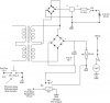
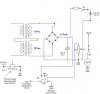
I thought I would complete this and finish the drawing.

This circuit was chosen because of the distance. Running conduit for the 120 vac from the control room was to expensive. So, I chose to run 30 vdc out at a distance of 75 ft using thermostat wire (Plenum rated) running in ceiling. Once it is at the destination it will have the 30 vdc relay closure for the 120 vac to run the light.

The purpose of this is to : To allow Students push button to talk ( Mute or Un-Mute ) ceiling mount Omni directional Microphones at the Mixer as needed.

kv

Thank you (Electro-tech-online) for the people willing to help here.

And in addition it would be appreciated if someone could inspect the drawing for mistakes.
 

Attachments

  • Send Fisished Drawing.jpg
    Send Fisished Drawing.jpg
    23.5 KB · Views: 123
Last edited:
hi kv,
There are a number of serious mistakes on the circuit diagram, dont build it as drawn.:)
 
hi kv,
There are a number of serious mistakes on the circuit diagram, dont build it as drawn.:)

Thank you Eric.

I'll go back over it. The prefab is working with my switch. I'll check the other drawings to see where it is. As well as this (one) I will admit I was in a bit of a hurry.

Valentines day a good bottle of wine and the wife with some delicious Mexican food all were beckoning for me.

I'm glad we have a longer edit time.

kv

hi kv,
Had a closer look at the drawing, there are so many errors its not feasible to correct your drawing.

I would suggest you get a low power mains transformer, with say a 24Vac secondary, rectified and smoothed you will get about 33Vdc which should OK to drive the 30V relay for the light.
It will also make the project a lot safer than using a non isolated mains supply.
 
Great.

Ok. So, Add a Transformer with 2 relay's and rectified smoothed circuit. ;)


This will also be cheaper. I have to do 3 more of these one light at the front and back of 2 rooms.


Thanks again. Eric


kv :D
 
Last edited:
Ok. So, Add a Transformer with 2 relay's and rectified smoothed circuit. ;)


This will also be cheaper. I have to do 3 more of these one light at the front and back of 2 rooms.


Thanks again. Eric


kv :D

hi,
Do you need a diagram.?:)
 
Would you suggest a dual out or would 2 transformers be simpler. Cost will not be important if it compromises quality.


kv
 
Would you suggest a dual out or would 2 transformers be simpler. Cost will not be important if it compromises quality.


kv

A low VA transformer, say about 6VA with a dual 12V-0-12V secondary will give about 200mA.

I wouldnt expect the 30Vdc relay coil to require a high current, so it should be well rated.

I would suggest you switch the 30V relay coil with then 5V relay contacts, you can connect any other switches in series with coil.

A 1N4001 diode across both relay coils would be a good idea.

OK.?
 
Last edited:
hi,
Look over this circuit.:)
 

Attachments

  • KVrelay1.gif
    KVrelay1.gif
    10.8 KB · Views: 239
A low VA transformer, say about 6VA with a dual 12V-0-12V secondary will give about 200mA.

I wouldnt expect the 30Vdc relay coil to require a high current, so it should be well rated.

I would suggest you switch the 30V relay coil with then 5V relay contacts, you can connect any other switches in series with coil.

A 1N4001 diode across both relay coils would be a good idea.

OK.?

Re-stated I have a combined Sharing center tap ov gnd 12v and 12v = 24v 200ma But, should render about 33vac. Bridge rectify then smooth it and switch 30v coil with a 5v then add the diode across it.

A good smoothing circuit would be great. Is there one I can copy or do you have something else in mind.

kv

Edit: I see the circuit. Thanks eric. And see the dual voltage (in) no ground
 
Last edited:
Thanks eric I'll giver another go.

470 cap is smoothing the circuit. I will draw another circuit. The port pin thing was a little miss leading.

What I remember talking to the company of the equipment I have a 3907 (or something) transistor pulling down pin 2 inside the equipment to ground. pin 23 is constant 5v and I have the Pb on 3-4-5. Which are assigned to them as a toggle from the all the PB in series parallel with them Pin 2 is the status of pin 3-4-5.

But, yes this will do nicely I will talk to the company to get the perspective on the pull down transistor to include it in my drawing maybe.

kv
 
Last edited:
Take a look.

When I went to the local dealer hear in town I was able to get the dual center tap transformer 24v cener tap @ .5a ma I purchased 3. I need 4 total he also had another 24v center tap @ 1a . and I purchased that also.

He only had Relays with 24v coil @ 1100Ω I purchased them with (dpdt) intending on using the voltage off the center tap to drive a small LED switching it off the other set of contacts. Maybe using the diagram below or.....

Maybe instead of using the regulator drop the voltage halfwave rectify and use a 180 Ω resistor ? I don't know if that's even possible

Or just use a separate power supply for the Led. But it just seems so redundant.


kv
 

Attachments

  • Reveiw Circuit Electro-tech.com.jpg
    Reveiw Circuit Electro-tech.com.jpg
    33.7 KB · Views: 116
Last edited:
When I went to the local dealer hear in town I was able to get the dual center tap transformer 24 v @ .5a ma I purchased 3. I need 4 total he also had another 24v center tap @ 1a . and I purchased that also.

He only had Relays with 24v coil @ 1100Ω I purchased them with (dpdt) intending on using the voltage off the center tap to drive a small LED switching it off the other set of contacts. Maybe using the diagram below or.....

Maybe instead of using the regulator drop the voltage halfwave rectify and use a 180 Ω resistor ? I don't know if that's even possible

Or just use a separate power supply for the Led. But it just seems so redundant.


kv

hi kv,
When you say dual 24V centre tap, do you mean 24v 0v 24v..????

Why cant you use the dc voltage on the 470uF to drive the led thru a suitable resistor.??


EDIT:
you could also connect the resistor and led in parallel with the 30V relay coil.
 

Attachments

  • Reveiw Circuit Electro-tech.com.jpg
    Reveiw Circuit Electro-tech.com.jpg
    33.3 KB · Views: 107
Last edited:
Like it.

Excellent.


Thanks a bunch. Eric.


kv:)


Edit: Oh, it's a 12 .0. 12
 
Last edited:
What gives ?

I try to post this and removed it because I wanted to double check the circuit.

So, with my cap out of circuit I'm at about 34volts with it in about 47 volts on This transformers is rated at .5a

Then I have a transformer rated at 1.0a and is about 44 volts when removed drops to the desired voltage of around 33-34v.


kv

hi kv,
I think I follow,:)

Cheaper transformer will give unexpected voltage results when 'off load' compared to the expected voltage when fully 'loaded'.

This 'poor' regulation is due to cheap transformer construction.

If the 'on load' voltage is too high for the 30V relay, add a suitable value resistor in series with the relay coil
[ dont forget to consider the resistor wattage]

If the 'off load' voltage is too high for the smoothing cap, add a load resistor across the cap.
As you are running the application from the mains the loss in the resistors will not be a problem.
 
Last edited:
hi kv,
I think I follow,:)

Cheaper transformer will give unexpected voltage results when 'off load' compared to the expected voltage when fully 'loaded'.

This 'poor' regulation is due to cheap transformer construction.

If the 'on load' voltage is too high for the 30V relay, add a suitable value resistor in series with the relay coil
[ dont forget to consider the resistor wattage]

If the 'off load' voltage is too high for the smoothing cap, add a load resistor across the cap.
As you are running the application from the mains the loss in the resistors will not be a problem.

I thought maybe it had something to do with my cap. The guy only had some 50v caps in stock about 1/2 inch across and 1 inch tall or so.

I also wondered if the may have been to large ? Like the plates to far apart or something.

But measuring straight off the rectifier it's at 34v and then with the cap in circuit it bounces to 44-47v. I did measure with my meter leads on each side of the coil in load it drops to 36v ? This had me so confused.

I had been told by others going up some in voltage on a cap wasn't to bad it was the microfarad was critical.

But, that all changed after being on this site for a year. I've reading so much stuff my head has gotten more info but most of it is like peace's of a big puzzle.

The more I know the less I understand.

kv:rolleyes:
 
I had been told by others going up some in voltage on a cap wasn't to bad it was the microfarad was critical.

But, that all changed after being on this site for a year. I've reading so much stuff my head has gotten more info but most of it is like peace's of a big puzzle.

hi,
On this application, providing a caps rated working voltage is greater than the highest expected voltage applied to the cap, its OK.

The caps capacity rating ie; uF etc is the important parameter.

In your project the cap could be 220uF or 680uF, its not critical.

Use a 50Vdc wkg cap, add a 3K9 1W resistor across the cap, just to pull the 44~47V down a little. OK

BTW: the 3K9 could be used to drive a series LED at about 10~12 mA, make a simple power ON indicator.

Got it.


kv:)
 
Status
Not open for further replies.

Latest threads

New Articles From Microcontroller Tips

Back
Top