Continue to Site

Welcome to our site!

Electro Tech is an online community (with over 170,000 members) who enjoy talking about and building electronic circuits, projects and gadgets. To participate you need to register. Registration is free. Click here to register now.

  • Welcome to our site! Electro Tech is an online community (with over 170,000 members) who enjoy talking about and building electronic circuits, projects and gadgets. To participate you need to register. Registration is free. Click here to register now.

I have a new project which is a Tyre Balancer Machine

Status
Not open for further replies.

Gregory

Member
It is a 3 phase what wire goes where on the plug
 

Attachments

  • 101954D3-886F-4027-A67E-2C4D94494AC6.jpeg
    101954D3-886F-4027-A67E-2C4D94494AC6.jpeg
    100.9 KB · Views: 143
  • F433E03E-7C39-476B-AFB1-4574E0F0AFAE.jpeg
    F433E03E-7C39-476B-AFB1-4574E0F0AFAE.jpeg
    77.2 KB · Views: 141
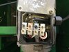
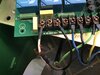
There seems to be an "E" and an earth symbol near the pin at the top of the photo, the pin nearest the location feature on the plug, so that is probably earth.

I can see "1" and "2" on two other pins, and I guess the other one is "3", so those would be the three live wires.

I would test that with a multimeter before plugging in.

There doesn't seem to be a neutral, which doesn't matter if all you are running is a motor, but there won't be a 220 V supply. Your machine may need a neutral, in which case you can't plug it in with that plug.

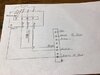
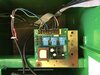
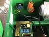
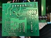
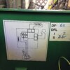
It's usual for three-phase motors to have a common point where all three windings join, that isn't connected to anything. It looks like you have that, and that three phase power is needed to the red, white and black connections on the motor. However, I'm not sure and I don't know what control circuits are there to turn the motor on and off.

The directions of the windings are important. The diagram shows red, white and black connections to the motor for power, and red, white and black connections to the common point. That makes me think that each winding has the same colour at either end of it. If so, is there anything to say which end should be common and which should be the power input? If you get one or two windings the wrong way round, the motor will take a huge current. (If you get all three the wrong way round, it's fine).

3-phase motors often have the winding wires brought out to two rows of three terminals, arranged so that power connects to the three terminals in one row, and the other row has all the terminals connected together. If that is the case, it doesn't matter which row has power, and which row has all the terminals connected together.
 
I do not want to connect the power supply the wrong way as there is electronic it’s in volved.
I need to be certain befor power is applied
 

Attachments

  • 0C993ECC-2B09-4048-B5A0-AA923693E833.jpeg
    0C993ECC-2B09-4048-B5A0-AA923693E833.jpeg
    1.7 MB · Views: 134
If I connect the motor will that tell me what wires go where . I know which direction the motor goes If I get this correct is that the way I wirer on the plug
 
I don't think that you've got enough information to be sure how to wire that. The electronics could need a neutral, and there doesn't seem to be a neutral in the plug.

For a 3 phase motor on its own, it will run if you connect the three phases to the three wires. It doesn't matter which connects to which, but it may turn in the wrong direction. Unless the mechanical system will get damaged by running backwards, it's standard practice to run it and see which way it goes. If it goes the wrong way, swap any two of the three phases.

Have you measured the voltages available at the socket you want to plug in to?
 
Would it be better to replace the 3 phase motor with a 240 v motor then run the whole system on 240 v Ac
 
Would it be better to replace the 3 phase motor with a 240 v motor then run the whole system on 240 v Ac
The OP has to find out if 240 V is needed for the electronics, as it might be that it runs from 400 V. The actual electronics will run from a low voltage through a transformer, so either 240 V or 400 is possible.

Where the power for the electronics is connected isn't clear either.

The plug appears no to have a neutral, so if the OP wants to use that, there will be no 240 V supply available. Admittedly, a different plug and a standard mains outlet may well be available.

All in all, a 240 V motor would not be solving the problems that the OP has.
 
Can you get more photos of the connections to the rest of the machine? A few more things that could help are:-
A photo of the motor connections
Make and model of the machine
Photo of the rating plate
Photo of the socket that it is to be plugged into
Voltages between all the pins of the socket that it is to be plugged into
 
Having talked to a electrical person and he told that it dos not matter about the 4 wires only the earth.
the 3 wires are all 240 volt each and if the mot r is going the wrong way just change 2 wires .
I will let you know how it goes. Thank you Greg The Electrical person he said tha the electronicies will Nt be damaged
If the machine doesn't need the neutral, and is not damaged by going the wrong way, then I would agree with all of that.
 
I have got the balancing machine going and the motor runs in the correct direction but the motor stops and and starts I have to turn the shaft to get it going.
I have tested the windings with a meter every thing is ok
There is 3 relays 240 volt could one of them be faulty. are the 3 relates for each phase .They are on the circuit board .
thank you Greg
 

Attachments

  • 004A96EB-4ECD-467B-9D13-643221B652FE.jpeg
    004A96EB-4ECD-467B-9D13-643221B652FE.jpeg
    1.8 MB · Views: 142
The behaviour of the motor is what you get when one phase is missing.

I think that the brown wire should be connected. That being not connected would cause the same behaviour as a failed relay.

Can you show the terminal markings on the circuit board? There seem to be four motor terminals. Is there any marking on them? I don't know why there would be 4 terminals with 3 phases and 3 relays.

Are you able to measure the voltages on the motor terminals when it is running? It would be useful to have the voltages to ground and the voltages between the terminals.
 
Also, if you need to turn the shaft to get the motor to run, you'll probably find that it will turn in either direction. When you get it to start as well as run, it may go in the wrong direction, and then you just swap two wires on the motor or the plug.
 
Can you post a good clear photo of the data plate on the side of the motor? That may clarify some details as well.
The "termination" on your drawing in the first post is puzzling; I wonder if it is a three phase motor, or capacitor run, or some other variant?

The wheel balancers I've see working tend to be very "gentle" in starting and accelerating, which is not what you would expect from a direct-on-line three phase motor.

I wouldn't have expected a three phase motor on a relatively small machine such as a type balancer - unless it's for balancing truck tyres?.
 
I will post photos . I have not done the voltages as yet Wil post them later.
 

Attachments

  • 2CE040FC-9B91-41E3-84FC-C9D0BB0EAC91.jpeg
    2CE040FC-9B91-41E3-84FC-C9D0BB0EAC91.jpeg
    1.7 MB · Views: 144
  • A52FF494-F43E-4258-96CB-86F2E555DE48.jpeg
    A52FF494-F43E-4258-96CB-86F2E555DE48.jpeg
    938.8 KB · Views: 261
  • 07643547-58C5-47E4-8CE9-49B09BB1AD7D.jpeg
    07643547-58C5-47E4-8CE9-49B09BB1AD7D.jpeg
    1.5 MB · Views: 132
  • 00A17529-3459-4DBA-9F05-0898A023005D.jpeg
    00A17529-3459-4DBA-9F05-0898A023005D.jpeg
    1.6 MB · Views: 138
  • 3C4DF8E5-CFCE-4561-BD00-DB47E3616B3C.jpeg
    3C4DF8E5-CFCE-4561-BD00-DB47E3616B3C.jpeg
    1.8 MB · Views: 126
  • B98A00EC-38BE-49FF-89F9-E4CCF66BA20D.jpeg
    B98A00EC-38BE-49FF-89F9-E4CCF66BA20D.jpeg
    1.7 MB · Views: 130
  • E1A0C2EA-4AD8-4251-83EF-F4747BD3B84C.jpeg
    E1A0C2EA-4AD8-4251-83EF-F4747BD3B84C.jpeg
    631.1 KB · Views: 143
The last photo with the outline diagram clearly shows a single-phase power system, using what appears to be a capacitor-start (or run) motor.
Thought the board is labelled for three phase... Possibly a difference between external power and the motor functions.

Is the big power resistor it shows still fitted somewhere? it does not appear to be connected to the board.
That is likely the "soft starting" resistance and without that it may only kick rather than running smoothly.

You have not included one of the motor plate itself - can you add that please?


tyre_balancer_2.jpg
 
Last edited:
I have removed the transformer from the board as smoke started to come out of the transformer .
how do I test this transformer I will post a photo of the transformer .
also there is a track missing under the transformer. I will post a photo of the transformer . There is no information on the transformer.
 

Attachments

  • BBD5D142-152B-49BC-B277-12F9044E7C6B.jpeg
    BBD5D142-152B-49BC-B277-12F9044E7C6B.jpeg
    168.5 KB · Views: 110
  • F4F3DBC2-C288-4BE9-8BC3-7644C460F7DC.jpeg
    F4F3DBC2-C288-4BE9-8BC3-7644C460F7DC.jpeg
    2.2 MB · Views: 113
  • 7EFF0D40-1CE7-43EF-9F0B-E86350658650.jpeg
    7EFF0D40-1CE7-43EF-9F0B-E86350658650.jpeg
    631.1 KB · Views: 110
Status
Not open for further replies.

Latest threads

New Articles From Microcontroller Tips

Back
Top