Continue to Site

Welcome to our site!

Electro Tech is an online community (with over 170,000 members) who enjoy talking about and building electronic circuits, projects and gadgets. To participate you need to register. Registration is free. Click here to register now.

  • Welcome to our site! Electro Tech is an online community (with over 170,000 members) who enjoy talking about and building electronic circuits, projects and gadgets. To participate you need to register. Registration is free. Click here to register now.

I have a new project which is a Tyre Balancer Machine

Status
Not open for further replies.
It seem to be a three-phase motor, but the diagram show only two supply wires and what seems to be a capacitor connected to the motor.

Three-phase motors are quite often run from two wires with a capacitor added to the third wire of the motor. It's a perfectly good way of running a motor. The power and efficiency will be worse, but that doesn't matter for this application. The size of the capacitor can be adjusted to give the starting torque that is wanted, so it is quite possible that the design chose using a capacitor to make the motor start more gently. As others have said, a three-phase motor started directly from at three-phase supply will have a big start torque, and there isn't an easy way to limit that.

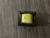
However, without a capacitor, there will be no start torque, and the motor will do what you have described, in that it will need a push to get going. Something needs to be connected to the third motor wire to make it start correctly. Is there a capacitor anywhere near the motor? It will be cylindrical, maybe 3 - 5 cm diameter, 5 - 10 cm long.

The resistor in the diagram is probably a braking resistor. It makes sense that some sort of braking will be needed as without it the wheel will just keep turning. I think that one of the relays is to run the motor, and two are to control the braking. As far as I can tell, the black supply wire is connected directly to the blue motor wire, so at least one motor wire isn't switched, therefore the three relays are not being used to switch the three phases. Also, if three phases were being switched, a single relay with three contacts would be used.

In the thread about running three-phase motors from single phase, that you contributed to, I posted a picture of single relay used to switch a three-phase motor:- https://www.electro-tech-online.com...atic-miller-system.100563/page-7#post-1309053
 
After looking through about fifty or so service manuals, I've found one that has the exact same block diagram for the power system.
It's a different control panel arrangement, but that is pretty irrelevant.
Unfortunately no makers infor or full wiring diagram..

See page 19:

The machine that relates to:
 
Possibly also sold as a Century CEN-900 ??

It may be worth contacting the site https://centurydistributors.co.nz/ to see if they have a wiring diagram for that machine?

I suspect some parts have been swapped around in that and the motor is not the original.

The first manual mentions changing a couple of components to
change the supply voltage for the unit - a capacitor, resistor and a different motor.

The resistor may be the one in the middle of the board near the terminals, as that appears to be connected to the transformer primary?

The motor may have been changed to the wrong type as part of an attempt to change the machine to a different supply voltage.
The motor says 380V but apparently the circuit board is not configured for that supply...
 
Diver:
Re. the braking, one of the relays is used to switch power from the bank of diodes to what appears to be the NC on one of the motor power relays.

It may? work with the third motor wire connected to the presently unused terminal between the black and blue wires - that is definitely used for something.

But if it is supposed to be a capacitor run motor, the two different switched outputs could even have been different directions...
 
Is it possible to change this system to 240 volts ,if so could someone post a circuit digram.
can I use the circuit board.
thank you
 
Just searched using the part number of the power board and found this - it shows the motor interconnections better.
It's yet another version of the "computer board" but apparently the same motor power one?

If this is accurate, the missing connection from the middle PCB terminal to the third motor wire is for the DC brake limiting resistor and the motor should be a capacitor run type.

That motor may work if reconfigured from star to delta and a suitable capacitor added.
 
I don't have any diagrams - I spent a couple of hours searching through every "wheel balancer service manual" that I could find online.
The above links are the only relevant bits I could find...
 
No, it seems to be a generic type that is rebranded by whoever distributes or sells them.
The manuals that seem to match it have no manufacturer info included, presumably so each rebrander can claim it as their brand.

The only definite name link appears to be the Century Distributors place, who seem to sell things from that manufacturer (whoever it is).


I'd try adding the motor capacitor to see if it will then run (between the black and brown motor wires). Don't connect the brown to anything else yet.
 
I will try that using 240 v is that ok.
can you describe how to test the transformer.
 

Attachments

  • 2233A237-AE23-474A-88A3-6C6E6C3B04D1.jpeg
    2233A237-AE23-474A-88A3-6C6E6C3B04D1.jpeg
    2.6 MB · Views: 100
If you are reducing the supply voltage, I'd just try the transformer back in the PCB and see if it works!

Just be sure to fit it the correct way around; from the PCB layout, the primary appears to be connected to the two end pins on one side and the secondary uses the end pins and centre pin on the other side.

The primary will be the higher resistance one & goes to the outer edge of the PCB.
 
I have noticed that the SMP Transformer has a broken wires on the secondary how can I find out the information about the trans former . Please
 
I don't think it is an SMPS (switch mode power supply) transformer. I think that it is a conventional 50 Hz transformer.

If you can trace the circuit it will help. A photo of the top of the board would be useful.

SMPS transformers are really hard to find replacements for. Conventional transformers are much easier to find a functional equivalent, even if it doesn't fit.

However, it might be easier to buy a complete power supply and wire that it.
 
There is a photo on page one this may help you . Could you tell me what type of transformer it is. The secondary wire is the thicker wires of the transformer. There is a centre tapping and the ohm reading is 2.5 on one side and 2.3 on the other half and 4.2 total with the meter.
the secondary has broken wires . The wire is very thin. but I will try to get a reading.
thank you.
 
Last edited:
It's a conventional 50/60Hz transformer, connected to the board AC input; it appears to be via a resistor, possibly to allow higher voltage supply than the transformer is rated for or possibly just surge limiting.
 
There is a photo on page one this may help you . Could you tell me what type of transformer it is. The secondary wire is the thicker wires of the transformer. There is a centre tapping and the ohm reading is 2.5 on one side and 2.3 on the other half and 4.2 total with the meter.
the secondary has broken wires . The wire is very thin. but I will try to get a reading.
thank you.
I saw the photo of the underside of the board. There is only one connection visible to one row of pins, and I was trying to work out where there was another connection to that row of pins.

I agree with rjenkinsgb and I think that it is a 50 Hz centre-tapped transformer.

You say that the wires are very thin. That would be the primary, the side connected to the mains supply. Small transformers like that are very rarely made with 380 - 420 V inputs. The are almost always 100 - 120 or 200 - 240 V and they will take far too much current on 380 V and they will burn out quite quickly. They don't take twice as much current if the supply is twice as big, it's more like 10 times the current, because the core is saturated, and maybe 20 times the power, so a 220 V transformer will not last long on 380 V.

I guess that the machine needs a neutral so that there is 220 V available for the transformer, even if the motor is run from 380 V with no neutral.

I suggest that you get a toroidal transformer and wire that in place of the damaged transformer. You will need to mount it separately. I'm suggesting a toroidal transformer because toroidal transformers can be mounted with a single bolt and they come with wires, not terminals, so you can just solder the wires in the place of the pins of the damaged transformer. A low value fuse in series with the primary should protect the transformer if you get 380 V on it.

If you can tell us what's written on the capacitors near the transformer, and on the regulator that is on the heatsink near the capacitors, we can estimate the voltage of transformer needed. It won't matter if you get a transformer with a larger power rating than is needed, as long as the voltage is correct. The transformer that is damaged would have been 10 - 20 VA, so you can aim for somewhere around 20 VA. Larger transformers are bigger and cost more, but there isn't really any other downside. A 30 VA transformer is about £20 UK and weighs about 500 g.
 
The PCB is marked as being for 380V.
I think the transformer primary runs through the shiny wirewound resistor near the terminals, but it's difficult to tell with so much of the topside tracking being hidden.

IF it is the machine in that manual I found, only a resistor, capacitor and the motor need changing for use on different voltages - probably the motor run cap and brake resistor.

As you say, a separate transformer ( with fuses in both the primary and secondary wires) is the simplest and safest option.

The relays appear to be 5V, so I'd expect a 7-0-7 or 9-0-9 transformer secondary would be suitable - but knowing the types of both voltage regulator ICs and smoothing caps would allow that to be verified.


a52ff494-f43e-4258-96cb-86f2e555de48-jpeg.126311
 
This voltage regulator and capacitors are in the photo
 

Attachments

  • 42F538C7-C1B7-4B04-95A6-769A0D0DAAD3.png
    42F538C7-C1B7-4B04-95A6-769A0D0DAAD3.png
    293.1 KB · Views: 101
  • C22F9A47-76A5-4896-98A3-2DB7E48E12D5.jpeg
    C22F9A47-76A5-4896-98A3-2DB7E48E12D5.jpeg
    353.4 KB · Views: 107
Status
Not open for further replies.

Latest threads

Back
Top