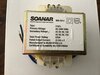
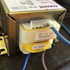
I have purchased a trans former will this one do the job .
That looks fine.
You must make sure that the supply isn't more than 240 V. You will need a neutral connection, not just the three phases. If you connect that transformer between two of the three phases, it will burn out.
You have to connect the 240 V to the correct winding. As far as I can tell, it will only have two wires, because there is only one voltage option for the input voltage, and the resistance between those two wires will be higher than the other windings, maybe 100 - 1000 Ohms. Having looked up that transformer, I think that it has wires for the 240 V connections and tags for the 0, 9 and 12 V, but check the resistance anyhow.
You have to work out which are the 9 V windings. It should be labelled. If not, they will be lower resistance than the 12 V ones. Alternatively, power up the transformer and measure the voltages.
The diagram that I found for that transformer shows two independent windings.
http://www.soanar.com/images/ocw/1247500_400_300.jpg
It's not clear from that how you connect the secondary. You will need to supply power to the transformer to find out. First check that you can measure 9 - 10 V ac between the 0 and 9 V connections on each winding. Then turn off, and connect the 0 V connection on the first winding to the 9V connection on the second winding. Then turn back on and check that you have 18 - 20 V ac between the 9 V connection on the first winding and the 0 V connection on the second winding.
If not, turn off, remove the connection you made, and connect the 0 V connections on the two windings together. Then turn back on and check that you have 18 - 20 V ac between the two 9 V connections.
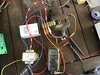
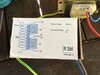
Whichever way gives you 18 - 20 V ac, you will have a common connection, and two wires are at 9 - 10 V ac from the common connection and they are 18 - 20 V ac from each other. That is how you leave it when connecting to the circuit board. The picture shows where the two 9 V connections and the common (0 V) connection go, as well as where the mains connections, L and N, connect.