Andrew Leigh
Member
Hi,
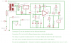
I have built this fridge thermostat (220V/12V/Gas absorption type fridge) which works perfectly but have a question or two.
- R6 sets the hysteresis, is it possible to calculate this value? R6 is currently 500k and when the temperature is selected it gives the set temperature +0.7°C, on reaching +0.7°C will drift back down the set point. I would like to decrease the range but experimentation is time consuming and would like to avoid this.
- I have taken my initial prototype board (waste not want not) and have converted it to operate the 12V element, at 175W this is a draw of 14,6A (only need this for limited durations, 4 hours or so). Is there such a thing as "starting current" with a resistive load? If so will an increased amount of switching increase the current consumption?
Regards
Andrew
")
