Hi all
I'm building a battery monitor and am having a problem with setting the to hysteresis points.
I've chosen the OPamp over say the like of the LM336 is that I Would like to have
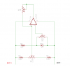
I'm trying to achive for the output of the OPAMP to go HIGH when the battery is 13.8V and only go LOW when it is 13.2V, The output could be inverted as I'm going to drive a opto-coupler, is it can be connected to either the pos or neg rail.
Some possible problems:
1: I've noticed that the voltage across the Zener is 5.88v and not 5.6v (but is stable when the battery voltage 10-15 volt, so doubt its that?)
2: The ouput is relative to the Vss/Vdd, hence the amount of feedback varies as the battery voltage increases? Should I use a reg to optain a constant voltage for the feedback?
3: If I'm correct, the hysteresis would be relative to the voltage dividing network on the Non-inveting input? Eg: say the feed back on the hysteresis resistor is 0.1 volt, and the network is divided to 5V, 0.1 volt is less feedback compared to 0.1V over say 3V from the resistor network?
Hope that all makes sence?
Please see attached schematic.
Thanks in advance
I'm building a battery monitor and am having a problem with setting the to hysteresis points.
I've chosen the OPamp over say the like of the LM336 is that I Would like to have
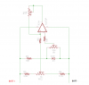
I'm trying to achive for the output of the OPAMP to go HIGH when the battery is 13.8V and only go LOW when it is 13.2V, The output could be inverted as I'm going to drive a opto-coupler, is it can be connected to either the pos or neg rail.
Some possible problems:
1: I've noticed that the voltage across the Zener is 5.88v and not 5.6v (but is stable when the battery voltage 10-15 volt, so doubt its that?)
2: The ouput is relative to the Vss/Vdd, hence the amount of feedback varies as the battery voltage increases? Should I use a reg to optain a constant voltage for the feedback?
3: If I'm correct, the hysteresis would be relative to the voltage dividing network on the Non-inveting input? Eg: say the feed back on the hysteresis resistor is 0.1 volt, and the network is divided to 5V, 0.1 volt is less feedback compared to 0.1V over say 3V from the resistor network?
Hope that all makes sence?
Please see attached schematic.
Thanks in advance