Continue to Site

Welcome to our site!

Electro Tech is an online community (with over 170,000 members) who enjoy talking about and building electronic circuits, projects and gadgets. To participate you need to register. Registration is free. Click here to register now.

  • Welcome to our site! Electro Tech is an online community (with over 170,000 members) who enjoy talking about and building electronic circuits, projects and gadgets. To participate you need to register. Registration is free. Click here to register now.

HTRC110 long range RFID Reader

Status
Not open for further replies.

abderr080

New Member
Hi everyone,

I am working on an RFID reader using HTRC110 with a coil antenna of 18cmx12cm but I could not get the desired range (at least 10cm) for a small tag 10*12mm like this one Hitag S 256 Pigeon Ring. In this document HTRC110 Application note I found out that I can use external power MOSFET-transistor pairs to drive more current to the antenna, but I dont know which mosfet to use or how to use it.

Does anyone know how to use HTRC with Mosfet transistors?

Another question: Is it also possible to use multiple antennas with single HTRC110 (only one antenna active at a time).

Thank you in advance.
 
Is the antenna properly resonant and impedance matched to the IC? That's the first part of getting it working at longer range, before increasing power.

Edit;
after looking at the device datasheet, the TX outputs have full supply voltage swing.

With MOSFETS, look at any smallish logic level (very low threshold) type devices that can handle 500mA to 1A; don't go for large ones as the gate capacitance is very high with power types.

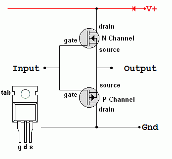
Try a P channel + N channel complementary pair with gates linked as input and sources as output, with drains to power and ground.
 
Last edited:
Thank you for your response.

Is the antenna properly resonant and impedance matched to the IC? That's the first part of getting it working at longer range, before increasing power.
I am a nebie to RF but i follwed all formulat to calculate all composants suggested in the circuit to get 200mA for the Antenna. my antenna has 385µH with 11Ω.

Try a P channel + N channel complementary pair with gates linked as input and sources as output, with drains to power and ground.
The input is TX and the output is Antenna?
 
TX1 and TX2 are the driver outputs of the HTRC110 IC, and they are designed to provide the power to make the coil resonate, but they can also be used to drive MOSFETS which in turn power the coil.

RX is the input to the HTRC110. The signal from the coil goes into the detection circuit that way.
 
I am a nebie to RF but i follwed all formulat to calculate all composants suggested in the circuit to get 200mA for the Antenna. my antenna has 385µH with 11Ω.
You need to look at the signal with an oscilloscope to be able to tune the antenna properly.

Calculations alone are often not adequate for RF design work when it comes to tuned components, there are always variations and component tolerances involved - that's why many mass-produced things with RF tuned circuits still need tuning capacitors or adjustable cores!

Getting the antenna right will increase both transmit and receive effectiveness.

The input is TX and the output is Antenna?
Yes, but if the antenna is not resonant more power many not help.

The IC itself can drive the antenna to a relatively high power, for such an application.
 
Hello everyone.

Thank you for your answers. I made a simple diagram (below) from what I understood from your explanations and I hope you will revise it for me.

Thank you

1684271629976.png
 
Low cost Network Analyzer that help bigly in Antenna and RF design :


Regards, Dana.
 
hope you will revise it for me.
You would need a complementary pair of MOSFETs for each TX output.

Something like this for each output; ignore the device pinout and diode:

MOSFET_Push_Pull_Amp.gif


The input of each buffer circuit connects directly to each TX pin, the other antenna coupling & matching components would then go to the outputs of the buffers instead of the TX pins.

(But it still needs the antenna setting up correctly, to work).
 
If you boost the output power to the antenna it will increase the reach of the signal but how will the HTRC110 be able to receive it back. The coil is bi-directional and isolating the receiver will prevent it working.

Brian.
 
Status
Not open for further replies.

Latest threads

New Articles From Microcontroller Tips

Back
Top