Continue to Site

Welcome to our site!

Electro Tech is an online community (with over 170,000 members) who enjoy talking about and building electronic circuits, projects and gadgets. To participate you need to register. Registration is free. Click here to register now.

  • Welcome to our site! Electro Tech is an online community (with over 170,000 members) who enjoy talking about and building electronic circuits, projects and gadgets. To participate you need to register. Registration is free. Click here to register now.

HT12E/HT12D

Status
Not open for further replies.

zachtheterrible

Active Member
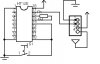
Ive seen other people asking about why the output of the HT12D latches. I never came across this problem until now, and its driving me nuts! It is a totally sporatic thing. When it latches, I can sometimes press the transmit button on the HT12E/transmitter and the output will go from low to high (active to inactive).

Can anybody shed some light on the subject for me?
 
Ive discovered why the HT12D is latching. As you see on my schematic, pin 10 and pin 14 are activated by closing the switch. Pin 10 is the data pin, and pin 14 is the TE (transmit enable) pin.

If pin 14 is held to ground, and not activated only when the switch is closed, everything works smoothly. When it is activated at the same time as pin 10, thats when things get messy. I would keep pin 14 grounded and everything would work fine, but the problem with that is when TE is enabled, it sends a signal to the RF module that it is attatched to continously, wasting battery power. The idea with the switch is that it only transmits when the switch is closed.

Anybody have any ideas as to how to do this?
 

Attachments

  • ht12e.jpg
    ht12e.jpg
    30.4 KB · Views: 2,649
Yes thats right russ. Im glad that I made myself clear enough. Wasn't sure if i did.

Since I don't know much about digital electronics, what are inverters? Can I do it with two transistors?
 
I figured Id give one more shot at trying to solve the problem my way and i did!!

I realized that it doesnt matter which pin gets activated first, the data or TE. In fact on the datasheet, it shows all of the data pins being a SPST switch, and the TE being a pushbutton switch, so that when the TE pin is activated, the data pins have already been activated.

The capacitor has to charge up before TE can be activated.

So what it basically comes down to is which will be cheaper and smaller?

BTW, I cant make the delay on any of the data pins because the TE pin will be activated right away, but the data pin might take too long to activate, and the signal won't get through. Also, I only have to do this on one pin, as opposed to doing it on each data pin that i use.
 

Attachments

  • ht12e_169.jpg
    ht12e_169.jpg
    34.7 KB · Views: 1,457
Cant the TE pin be used without having to club it with the data lines? I mean you can use TE independently, refer datasheet. I have never practically worked with HT12E/D, but I have studied the datasheet. So see if that's possible !
 
hi deer
please i need help in using a chip called HT12D
any one can help me please send emil to
myh75000@hotmail.com
hi fren..
My name is santosh gairhe and m n Engineering student form Nepal...
hab u got idea about how2 use Ht-12D...
I hab also bought it n m also having problem on using it.
my problem is .
when we just supply power 2 supply voltage does the Data out-put pin goes HIgh or not ?
What does it me by : the data out-put pin toggle....

Would u like 2 share ur knowledege with me?
 
hello frnds m new here, m stuck wid a problem, i made rf transmitter nd receiver but i m havn problem in receiver regarding power supply**broken link removed**

this is the circuit on which m working .dont know how to give power supply of 5v to ht12d nd the reciever............ would b glad if you would help me .
thank you
 
Last edited:
Hi guys, I need help to. I connected my 2 chips by this schematic : **broken link removed**

My questions are :
- how important it is that reciever and transmitter have the same value for antenna ( 50 Ohm ). My antennas have values like 50.3 Ohm and 49.7Ohm

- how important it is that resistor between oscillator pins is 1.1Mohm and 51kOhm
My values for this 2 are 1.07MOhm and 51.4kOhm

- when I connect by this scheme transmitter transmits and recievers seems to recieve something but on VT pin i got nothing
All my connections A0-A7 are left open

if you have any idea i will be gratefull
thanks,
miha
 
I’m trying to make out an application with HT12E & HT12D. but my Tx doesn’t send the data out. HT12E IC has power ON active high pins for A0~A7 & AD8~AD11. but I cant get high at any of those pins. To send the data, the Data pin has to be made ’0′. Im using TWS434 & RWS 434 RF modules for communication. What values or Resistors are suitable to work between HT12E & HT12D. I’m using supply of 4.5VDC each for both TX & RX. Pls help me…….naresh.pushpak@gmail.com
 
RF remote controlled Robot

hello,
can anyone help me...

i've recently finished my project titled "RF remote controlled robot".
actually the project is dc motor control using RF module and i've fitted wheels to the motors so it works as robot.
i'm attaching the abstract,circuit diagram

remote control transmitter part consists of 4 switches,based on which the controls are sent to the motor to rotate it in desired directions..
in my project i've pulled the TE(14 pin) of HT12E to gnd directly.....


now,my pblm is when i give the following commands at the switches the following is the result expected

0101-forward
1010-bckward
0001-left turn
0100-right turn
1001-left spin
0110-right spin
0010-left back
1000-right back

all these movements are working perfectly well....but only after some delay,

that is when i switch on the supply and press any switch the robot starts rotating in one particular direction and does not stop untill i manually stop it by switching off the power supply (even though i remove my finger by just touching the switch).....same is the case with any switch for abt 3-4 min...

after i manually stop the robot several times...(in abt 3-4 min) everything will be fine

soon after i touch a switch and leave the robot stops and the output is perfect for the above mentioned commands

i dont understand why there is this start up pblm?

can anyone pls help me?
 

Attachments

  • robot with receiver module on board.jpg
    robot with receiver module on board.jpg
    136.8 KB · Views: 337
  • rf transmitter module.jpg
    rf transmitter module.jpg
    121.3 KB · Views: 387
  • wireless motor control through RF.pdf
    223.5 KB · Views: 443
Status
Not open for further replies.

Latest threads

New Articles From Microcontroller Tips

Back
Top