hi C,
Cleaned up the draft prog, added some comments.
Note: the UART print out, the '*' are output when the sync char '$' is missed, the string is dumped.
E
Cleaned up the draft prog, added some comments.
Note: the UART print out, the '*' are output when the sync char '$' is missed, the string is dumped.
E
Code:
'software uart receives data stream at 9600 baud And when char $ is detected we capture all bytes
'in array str1 until LF code.
'Then send these To the PC via hardware UART at 9600 baud
'COPY and PASTE this string.
'$GPGGA,123519,4807.038,N,01131.000,E,1,08,0.9,545.4,M,46.9,M,,*47?
'GGA Global Positioning System Fix Data
'123519 fix taken at 12: 35: 19 utc
'4807.038,N Latitude 48 deg 07.038' N
'01131.000,E Longitude 11 deg 31.000' E
'1 Fix quality: 0 = invalid
'1 = GPS fix (SPS)
'2 = dgps fix
'3 = PPS fix
'4 = Real ovle Kinematic
'5 = Float RTK
'6 = esovlated (dead reckoning) (2.3 feature)
'7 = Manual Input mode
'8 = Simulation mode
'08 Number of satellites being tracked
'0.9 Horizontal dilution of position
'545.4,M Altitude, Meters, above mean sea level
'46.9,M Height of geoid (mean sea level) above WGS84 ellipsoid
'empty field) ovle in seconds since last DGPS update
'empty field) dgps station id number
'* 47 the checksum data, always begins with *
Define SIMULATION_WAITMS_VALUE = 1
Define CONF_WORD = 0x3f41 'XTL
Define CLOCK_FREQUENCY = 4 'Changed from 12
AllDigital
Dim chr As Byte
Dim rxi As Byte
Dim txo As Byte
Dim ovl As Byte
Dim str1(42) As Byte 'save the data stream we need in here
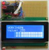
Define LCD_DREG = PORTB 'Port for LCD Data
Define LCD_DBIT = 4 'Use upper 4 bits of Port
Define LCD_RSREG = PORTA 'Port for RegisterSelect (RS) bit
Define LCD_RSBIT = 2 'Port Pin for RS bit (pin9)
Define LCD_EREG = PORTA 'Port for Enable (E) bit
Define LCD_EBIT = 4 'Port Pin for E bit (pin7)
Define LCD_BITS = 4 'Using 4-bit bus
Define LCD_LINES = 4 'Using 2 line Display
Define LCD_CHARS = 16 'ADDED
Define LCD_COMMANDUS = 2000 'Command Delay (uS)
Define LCD_DATAUS = 50 'Data Delay (uS)
CMCON = 7
OPTION_REG.7 = 0 'Enable Pull-Up's
CMCON = 7
OPTION_REG.7 = 0 'Enable Pull-Up's
TRISA = %00000000
TRISB = %01000000
INTCON.GIE = 1 'enable Global Intr
INTCON.PEIE = 1 'enbale Peripheral Intr
'''Lcdinit ' LCD not used in SIM
Hseropen 9600
PIE1.RCIE = 1 'enable UART RXD Interrupt
Hserout "Ready - await $", CrLf, CrLf
main:
'do whatever
Goto main
End
On Interrupt
Save System
Hserin chr
If chr = "$" Then 'test for string start character
rxi = 0 'rx data cntr
ovl = 0 'over flow counter
Endif
str1(rxi) = chr 'save chr in str1 buffer
rxi = rxi + 1 'inc buffer pointer
If chr = "?" Then 'test for LF code*** change to 0X0A in PIC prog
Hserout "Latitude: "
For txo = 14 To 15 'pick off Lat
Hserout str1(txo)
Next txo
Hserout "Deg "
For txo = 16 To 23
Hserout str1(txo)
Next txo
Hserout CrLf
Hserout "Longtitude: "
For txo = 25 To 27 'pick off Long
Hserout str1(txo)
Next txo
Hserout "Deg "
For txo = 28 To 35
Hserout str1(txo)
Next txo
Hserout CrLf
Hserout "Altitude: "
For txo = 46 To 52 'pick of Alt
Hserout str1(txo)
Next txo
Hserout CrLf
Endif
ovl = ovl + 1 'inc the over flow counter for every INTR
If ovl > 70 Then 'string is corrupt to dump it
For ovl = 0 To 70
str1(ovl) = "*" 'over write buffer with asymbol of your choice
Next ovl
rxi = 0 'reset counters
txo = 0
Endif
PIR1.RCIF = 0
Resume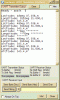

")
 ,
,