Continue to Site

Welcome to our site!

Electro Tech is an online community (with over 170,000 members) who enjoy talking about and building electronic circuits, projects and gadgets. To participate you need to register. Registration is free. Click here to register now.

  • Welcome to our site! Electro Tech is an online community (with over 170,000 members) who enjoy talking about and building electronic circuits, projects and gadgets. To participate you need to register. Registration is free. Click here to register now.

How to stop a DC motor?

Status
Not open for further replies.

Anthonyz

New Member
Hi guys...

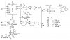
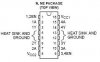
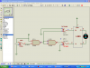
I am building a automatic hanger prototype for my project. I need to make my motor to move in a forward , stop and reverse pattern. When my hanger reaches the end of the railing it will have to stop. I am using H-bridge to control my forward and reverse movement. What should i add to make a stop mechanism?
 
you can have a switch that gets closed/opened when the hanger reaches the end. the cd drive trays use this mechanism IIRC.
 
If a voltage is applied to both sides of the motor it will stop so turn on the top two transistors of the H-bridge.
 
Last edited:
If a voltage is applied to both sides of the motor it will stop so turn on the top two transistors of the H-bridge.

Probably important to mention that the bottom side switches need to be off, if you do that. John
 
a not so gud solution would be to measure the time it takes to reach the end. You can make the motor turn off after that time.
 
**broken link removed**
 
You need to short across the motor, with an h-bridge, this is normally done by turning both top or bottom switches on at the same time.
 
I am trying to build something similar. I was going to use light to stop the motor at the spot I need. I used 2 resistors and a phototransistor for each stop point, then used gating to stop the motor. see attached. I seen no need for a h-bridge in my application so I used one 5 vdc dpdt relay to switch direction.
 

Attachments

  • door 4.jpg
    door 4.jpg
    94.6 KB · Views: 522
In order not to overstress the reduction gear the best way is already discribed. Short the motor. It stops more or less immediately.

If you want the mechanism to stop at a defined point you must check for a lead point and short the motor in advance.

Using IC contained H-bridges such as L298 (dual H-bridge) or TLE5206-2 (single H-bridge) just connect the limit switch between IN1 or IN2 and switch over to equal polarity.

No matter if the motor "sees" dual +VS or GND it will stop immediately.

I am using this technique for a sliding door and it works perfect.

Boncuk
 
I am using the L293 H-bridge. I have used up the En, 1A , 1Y , 2A , 2Y for forward and reverse purposes. Which pin should i connect my limit switch to make it stop?
 

Attachments

  • L293 H-bridge.JPG
    L293 H-bridge.JPG
    7.4 KB · Views: 343
I am using the L293 H-bridge. I have used up the En, 1A , 1Y , 2A , 2Y for forward and reverse purposes. Which pin should i connect my limit switch to make it stop?


Anthony,
First have a good read of the datasheet and you'll find that the En pins need to be high to enable the other pins to work. Now it aint rocket science to workout how to use the limit switch's now is it.:D
 
Hi Anthony,

this is how the L293 should be connected to the microswitches. Assuming R/H and L/H rotation the motor must be stopped turning either direction.

S1 selects R/H - L/H rotation.
MS1 is connected with NC to the logic output and C to 1A, NO is connected to ground
The same applies to MS2 which is connected to 2A, and also NO connected to ground.

To stop the motor (and any action) take 1,2EN to ground, otherwise always high.

I added three screenshots, L/H rotation, R/H rotation and stopping at when MS2 is depressed, switching 2A to ground. If both inputs have the same polarity the outputs follow correspondingly shorting the the motor to stop it.

Red indicates H-level and blue indicates L-level.

The L293 is no simulation model, it's just a drawing

Boncuk
 

Attachments

  • ROTATE LH.png
    ROTATE LH.png
    51.1 KB · Views: 304
  • ROTATE RH.png
    ROTATE RH.png
    52.6 KB · Views: 275
  • MOTOR STOP.png
    MOTOR STOP.png
    52.6 KB · Views: 276
Hi markjosef,

I can't follow your question. There are not four, but just three switches in the schematic.

All switches are labelled. S1 selects direction. Both limit switches act as brake switches if the motor reaches one of them. In all cases reaching a limit the voltage potential at the motor terminals are equal, thus shorting the motor for an immediate stop. Having reached the limit for R/H rotation the only logical way to run the motor again is L/H rotation which is achieved automatically.

Boncuk
 
Status
Not open for further replies.

Latest threads

Back
Top