Continue to Site

Welcome to our site!

Electro Tech is an online community (with over 170,000 members) who enjoy talking about and building electronic circuits, projects and gadgets. To participate you need to register. Registration is free. Click here to register now.

  • Welcome to our site! Electro Tech is an online community (with over 170,000 members) who enjoy talking about and building electronic circuits, projects and gadgets. To participate you need to register. Registration is free. Click here to register now.

How to parallel two 2N3055 transistors = 120vac, 150 watts?

Status
Not open for further replies.

gary350

Well-Known Member
I need to put 2 transistors in parallel for a total of 4 transistors so both transistors will each take 1/2 the current load in the circuit?

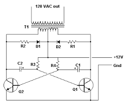
I already have a 4" x 6" heat sink with 2 transistors and the oscilator circuit. The circuit runs on a 12 vdc car battery, output is to a 250 watt step up transformer that produces 120 vac. It will light up ONE 60 w light bulb bright or ONE 100 w light bulb dull orange. This flip flop inverter circuit does not seem to work very well.

I down sized the light bulbs in the camper trailer to four 15 and 25 watts each but we also need a light bulb at the picnic table. National parks have no electricity so I take along a 650 amp hr battery that will last 7 days without being charged. We only need electricty for about 2 hours after dark.

I already have a dozen 2N3055 transistors so all I need to do it add 2 more transistors to this circuit. Maybe a better circuit is a better solution to the problem?


How Big is your Transformer?

That is a VERY BASIC Inverter Circuit.
And NOT VERY GOOD!

Your Two, 2N3055's should have a High Enough Rating for the 100 watts.

It is More Likely your Transformer is going into SATURATION, Rather than a Transistor problem.

Also, Inverter Transformers should have the 12-0-12 Winding, BIFILAR WOUND on the Core, With the 110 Winding Over the 12-0-12.

It would probably be Better to just BUY a 150 Watt Inverter.
They are QUITE COMMON and Not very Expensive.
 
I tried 2 different transformers one is 250 watts the other is 500 watts. They are both 120 vac step down to 24 v with center tap 12-0-12. I connected two 75w light bulb and blew the transistors. I probably need a fuse in the circuit.

Yea I could buy one at Harbor Freight but I have a lot of parts that are all free and I am having FUN playing.
 
Last edited:
Do you have HEAT SINKS on the Transistors?
THEY ARE NECESSARY.
 
What is your frequency of oscillation? A line frequency transformer will have very high core loss at a few kHz or higher.

Also, look at your input current waveform. I expect that the transformer inductance is high enough that it's limiting the input current.
 
The problem appears to be that the base drive resistors don't provide enough current to keep the transistors in saturation at the higher currents.

You could lower the values of R3 and R4 but that would increase there dissipation. You might try 100Ω, 1W or 2W resistors in place of the 180Ω

Another solution is to make each transistor into a Darlington stage by adding a transistor to increase their gain.
Connect the collector of the added transistor to the collector of the 2N3055.
Remove the 2N3055 base connection and connect it to the emitter of the added transistor.
Connect the new transistor base to the wire removed from the base of the 2N3055.
The added transistors can be the 2N3055s you already have.
The disadvantage of this is that it increases the power dissipation in the transistors since they now don't fully saturate when on.

A third solution would be a MOSFET design, which would be more efficient.
 
......................
Also, look at your input current waveform. I expect that the transformer inductance is high enough that it's limiting the input current.
The transformer inductance determines the magnetizing current, it does not limit the operating (input) current.
 
I dont know the frequency of this circuit and I have no scope.

I was wondering if I could use a 555 timer to turn on/off the 2N3055 transistors?

I can use a variable resistor on the 555 timer to adjust pulse width from 10% to 90% ON. I should be able to dial in the correct pulse width for best output of the transistor. I can also adjust the 555 timer for 60 Hz.

Is there a better circuit?
 
Wouldn't it be cheaper just to buy an inverter?

YES it would be cheaper, Harbor Freight has one $27 for 300 watts. Amazon has one $24 plus postage for 300 watts.

But I have 1000s of parts that need to be used for something. If I don't use the parts then I don't need the parts. I have been collecting parts for 45 years. I checked prices on ebay I could probably sell what I have for left for $20,000. I already sold some, 11 used NL7171 tubes, 6 810 tubes, 20 very large variable capacitors, 6 410mfd 5KV 18000 amp high energy storage capacitors, several variacs 500w to 10KW, several 600volt 600amp diodes, several 800 watt SCRs, 6 Tesla Coils from 150 watt to 12KW, 30 neon sign transformers, 5KW transformer 240/480 volt, 100KW transformer 240/14000 volt, 64 old TV power transformers, speakers, turn tables, amplifiers, vacuum tubes, so far I can not tell anything is missing. LOL. I need the floor space more than I need this stuff.

Yes I read #7. I could try that but what frequency will it be? I am not sure what frequency I have now. If the frequency is too far off it wont work well with a 60 Hz transformer. Hey thats an idea maybe that is what is wrong with this circuit Hz is to far from 60 Hz?
 
Last edited:
........................
Yes I read #7. I could try that but what frequency will it be? I am not sure what frequency I have now. If the frequency is too far off it wont work well with a 60 Hz transformer. Hey thats an idea maybe that is what is wrong with this circuit Hz is to far from 60 Hz?
The frequency is not critical for lighting incandescent bulbs as long as it's above 60Hz. It's frequencies below that which can cause the transformer to saturate.
My simulation with your circuit with the added Darlingtons had a frequency of around 60Hz but that was with a resistive load and didn't include any possible affects that the transformer might cause.
You might try reducing the value of the capacitors some (say to 47μF) to increase the frequency, just to be on the safe side.

P.S. Do you have any Tesla Coils left for sale?
 
The circuit you found DOES NOT WORK. There is a very long thread about its problems on Aaron Cake's site. We also laughed at it on Electronics Lab site.
1) Its capacitors have their polarity backwards so they blow up.
2) The transistors have avalanche breakdown when the capacitors drive the bases negative which also destroys the capacitors when their polarity is corrected.
3) Already said, the resistors cause the base current to be much too low.
 
But I have 1000s of parts that need to be used for something. If I don't use the parts then I don't need the parts. I have been collecting parts for 45 years. I checked prices on ebay I could probably sell what I have for left for $20,000. I already sold some, 11 used NL7171 tubes, 6 810 tubes, 20 very large variable capacitors, 6 410mfd 5KV 18000 amp high energy storage capacitors, several variacs 500w to 10KW, several 600volt 600amp diodes, several 800 watt SCRs, 6 Tesla Coils from 150 watt to 12KW, 30 neon sign transformers, 5KW transformer 240/480 volt, 100KW transformer 240/14000 volt, 64 old TV power transformers, speakers, turn tables, amplifiers, vacuum tubes, so far I can not tell anything is missing. LOL. I need the floor space more than I need this stuff.

So you've been digging around in my shop huh? :facepalm:

Good thing you haven't found the 'good and valuable stuff' yet! :D
 
I tried 2 different transformers one is 250 watts the other is 500 watts. They are both 120 vac step down to 24 v with center tap 12-0-12. I connected two 75w light bulb and blew the transistors. I probably need a fuse in the circuit.

Well ideally if you want to convert 12 VDC into ~120 VAC you need to start with transformers with a roughly 9 - 0 - 9 secondary not a 12 -0 - 12.

Secondly 2n3055 transistors are good to about 15 amps peak without killing them.

Third you need at least a little bit of off time between each half of the switching cycle.

Now that said I think that going with a 555 based driver circuit is a fair idea. I built a 1 KW+ power inverter back in highschool about ~23+ years ago when I was 17 and used 2n3055 transistors for the switching devices. If I recall I used something like 10 2N3055's per side with 9 being the primary switching devices and the 10th one being the driver for all of their bases.
Ahead of those I think I also ran an actual darlington transistor on each half of the circuit so the initial turn on currents coming off the driver board were pretty low.

Now with the 555 if you use the output to do the set/reset triggering you can get a nice clean 50/50 duty cycle with only two resistors and a capacitor.

I don't recall the exact circuit design I used but it was surprisingly efficient even when running high wattage loads. The only down side was it had no real voltage regulation but I had compensated for by using a old heavy duty6/8/12 volt battery charger transformer in reverse for the power transformer and that had something like 9 taps to work with so dialing up my output voltage for the given load and input voltage sag was easy.
 
The circuit you found DOES NOT WORK. There is a very long thread about its problems on Aaron Cake's site. We also laughed at it on Electronics Lab site.
1) Its capacitors have their polarity backwards so they blow up.
2) The transistors have avalanche breakdown when the capacitors drive the bases negative which also destroys the capacitors when their polarity is corrected.
3) Already said, the resistors cause the base current to be much too low.


You are probably right. I can not find my original circuit drawing so I did an online search and this likes like it. I have not worked on this project in several months. I dont think my circuit has any diodes or resistors R1 and R2. All I have left is the heat sink with 2 transistors and the transformers. So I need to find my original circuit or find a different one that works.

Sorry crutschow I sold all my Tesla Coils. The person that bought my 12KW TC was offered $5000 but he wont sell it.

I found this darlington circuit. I will try this.

upload_2015-2-16_17-0-25.png
 
Last edited:
Status
Not open for further replies.

Latest threads

New Articles From Microcontroller Tips

Back
Top