Continue to Site

Welcome to our site!

Electro Tech is an online community (with over 170,000 members) who enjoy talking about and building electronic circuits, projects and gadgets. To participate you need to register. Registration is free. Click here to register now.

  • Welcome to our site! Electro Tech is an online community (with over 170,000 members) who enjoy talking about and building electronic circuits, projects and gadgets. To participate you need to register. Registration is free. Click here to register now.

How to Multiply two Signals by simple components

Status
Not open for further replies.

Traveller30

New Member
Hi
My English is not the best 'so I apologize in advance.
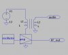
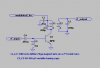
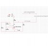
I’m trying to build a simple AM transmitter, there are a lot of circuits for doing that, but I’m trying to understand what I’m building and not just combine parts from a drawing.
I learned how a Colpits Oscillator works, and how to get Audio signal from microphone,
But I just can’t find how do I get these signals together to form an AM signal.
What I mean is, if I have two signals
SignalA: sin wave from an Oscillator SigA = sin(w_c*t)
SignalB: input from microphone SigB =sin(w_v*t)
How can I combine them to an Output in the form of (A+M*sin(w_v*t))*sin(w_c*t) using only capacitors , inductors, resistors and transistors? how they do that in real AM transmitter ?
Thanks in advance
 

Attachments

  • AM_Question.JPG
    AM_Question.JPG
    143.3 KB · Views: 1,085
In a practical AM transmitter it's easier than it seems. In an AM CB radio, when switched to transmit, the audio amplifer output transformer secondary is disconnected from the speaker and transferred to the supply rail that powers the transmitter output stage. When there is silence, the supply current passes through the secondary as though it was a peice of wire, the transmitter receives 12 V.

This is called "high level modulation". It's the most economic way when there's already an amplifier and transformer. When speaking, voice-shaped currents from the transformer secondary vary the supply voltage of the transmitter output stage. If the voltage swing on the transmitter supply rail reaches +24V and 0V, there would be 100% modulation.

OK, you can low-level modulate, synthesise the AM signal with a multiplier IC, but if the modulator is followed by RF amplifier stages, they have to be designed to behave linearly, otherwise the modulation is distorted.

It all depends on what the application is, to decide what's best for your circuit, can you post some more info?
 
Last edited:
You probably know that an amplifier is a multiplier, that the output is the input multiplied by the gain of the ampflier. So, then, one way is to use the other input to vary the gain of the amplifier. This can be done by varying the voltage supplying the amplifier output stage.
Also, there are voltage controlled amplifiers.

See this app note describing the internal working of one such multiplier.
https://users.ece.gatech.edu/~lanterma/sdiy/datasheets/multiplier/mc1496apnote.pdf
 
that was a little hard to understand...

tnx for the respond
but I need some help to understand what you wrote...

1) "when switched to transmit, the audio amplifer output transformer secondary is disconnected from the speaker "

did you mean that the transformer output is disconected from the speaker in the second stage of the transformer?

2) what you mean by "supply rail" ?

3)"OK, you can low-level modulate, synthesise the AM signal with a multiplier IC"
What do you mean by that? What I want is to synthesise the INPUT from the microphone with the Oscilattor wave.and I have no idia how to do that...i

4)"It all depends on what the application is, to decide what's best for your circuit, can you post some more info?"
the application is to learn and than built a simple AM transmitter.
there is no real important material application,these is why I try to understand how it works ,and only than build one,the level of moodulation is not important to me
 
In any AM transmitter the output frequency, or carrier frequency is modulated by the audio or voice frequency. AM stands for amplitude modulation. In simple terms the carrier frequency's amplitude is varied at the audio frequency rate. The output power varies from 0 to greater than the unmodulated carrier frequency, and this depends upon the percentage of modulation. For 100 percent modulation the output power would be 150% of the unmodulated carrier.
About the simpliest way I can think of achieving this is to have a buffer amplifier after the oscillator, and vary the supply voltage of the buffer amplifier. The buffer is necessary as if you vary the supply voltage to the oscillator the frequency becomes unstable(the oscillator will vary in frequency).
 
A non-linear amp has a transfer function something like this:

Out = C*e^vbe/vT

Lets look at the exponential:

e*x = 1 + x + 1/2*x^2 + ...

Now, let's look at the 3rd term of the Taylor series, and let x= cosw1t + cosw2t

where w1 is the modulating signal and w2 is the carrier signal

(cosw1t + cosw2t)^2 = cosw1t^2 + 2cosW1t*cosw2t + cosw2t^2

Look at the middle term ( the first and third terms are rejected by the circuit )

cosw1t*cosw2t: thus multiplication is achieved by exploiting the non-linear components of the amplifier.

The real expression for AM is: (1 + coswmt)coswct; where wm is the modulating signal and wc is the carrier signal.

Can the above analysis be modified to get the last result?
 
Last edited:
After thinking about it, I am able to answer my own question. But I'll give others a chance to do so first :)

Ps, I got an "A" in modulation, but I think Bush was still pres. then. I mean the first pres. Bush!
 
Last edited:
you need an oscillator at the frequency you want and an RF amplifier. instead of just hooking up the amplifier to the power supply, you run the power through a transformer secondary as shown. the audio goes into the primary of the transformer. as the secondary voltage swings, it changes the power supply voltage to the amp, and so changes the amplitude of RF at the output of the amp. it's as simple as that.
 

Attachments

  • am_xmitter.jpg
    am_xmitter.jpg
    14.1 KB · Views: 681
did you mean that the transformer output is disconected from the speaker in the second stage of the transformer?

what you mean by "supply rail" ?


unclejed613 answered those I believe :)

"OK, you can low-level modulate, synthesise the AM signal with a multiplier IC"
What do you mean by that? What I want is to synthesise the INPUT from the microphone with the Oscilattor wave.and I have no idia how to do that...


I mean with a 1496, or a dual-gate mosfet are 2 great ways of low-level modulation. Low level modulation means sythesising AM signal from a microphone and oscillator wave. I believe there are examples in 1496 datasheet how to do that, by applying an X and a Y signal or something. Been a while since I used a 1496. I prefer dual gate mosfet as a low-level modulator, you drive the audio into G2, and the RF into G1.

the application is to learn and then build a simple AM transmitter. <..> try to understand how it works ,and only then build one,
I think we've got all the info here now (in some form or other). The first AM transmitter I built (must be over 30 yrs ago!) was high level mod., I think you should too, it's easier than low level.
It looks like you make an RF (unmodulated) oscillator, which I beleive you already have. Add an RF amplifier after it (if it's needed). This is your 'transmit section', that will have an antenna attached and transmit a CW carrier unmodulated. Then add highlevel mod. just like unclejed613 picture described above. The Mic will need a power amp after it with high level mod.

the level of modulation is not important to me,
Page full of calculation theory not important to me neither. If it's over-modulated you'd hear it and you just turn down the volume.
 
the output stage amplifier is usually run class C, which means it produces pulses at the RF frequency. a tank circuit (tuned circuit) restores the waveform to a sine wave. look up "class C RF amplifier schematic" on google or wikipedia. a class C is usually the simplest, because it doesn't need a large heat sink or a bias circuit, just a transistor, the tuned circuit, and a couple other parts. something like the drawing below.....
 

Attachments

  • class-c.jpg
    class-c.jpg
    17.9 KB · Views: 921
Last edited:
About the simpliest way I can think of achieving [lo level modulation] this is to have a buffer amplifier after the oscillator,.

Dual gate mosfet makes a good buffer and modulator combined in one. gate 1 = osc gate 2 = dc bias of 1/2 supply voltage, plus capacitave coupled audio (at a few volts peak to peak)
 
tnx for the answers

tnx to all who answered
I'll try to get some sense out of it during the week
My work week have started again,so I'll do some testing in the next weekend to see if I can get something to work
Ill probably have more questions than...

tnx guys
 
I went through some literatures and came through an idea that a class C amplifier with a tank circuit at its collector output can perform frequency multiplication. How can I be able to select a multiplication factor either x2 or x3 etc.?

and generally how could I make it a wideband?
 
I suggest you make your question a seperate thread. I think there is an option to do that when you chose to edit you posting.
 
Okay.., I want to design a wideband frequency multiplier circuit employing the use of class BJT amplifier with a tank circuit at its output. How can I attain the multiplication factor I desire, and make it operate at a wide frequency range...???
 
one minor detail... tank circuit≠wideband

the best way to do it as a wideband method (depends on how "wide" of course) would be to use a PLL that operates at a multiple of the input frequency. you would use a class C amp to distort the input waveform, then high pass filter it so ONLY harmonics are passed, then use that signal as the reference for the PLL. this is really getting beyond the bounds of the original topic, and should be restarted as a new topic. the original poster was talking about ANALOG multiplication, more specifically TWO-QUADRANT multiplication or Amplitude Modulation, not frequency domain multiplication. maybe a moderator could referree this???? in any case i would be more than glad to answer your question better if you started a new thread about this subject.
 
Status
Not open for further replies.

Latest threads

New Articles From Microcontroller Tips

Back
Top