Continue to Site

Welcome to our site!

Electro Tech is an online community (with over 170,000 members) who enjoy talking about and building electronic circuits, projects and gadgets. To participate you need to register. Registration is free. Click here to register now.

  • Welcome to our site! Electro Tech is an online community (with over 170,000 members) who enjoy talking about and building electronic circuits, projects and gadgets. To participate you need to register. Registration is free. Click here to register now.

How to drive this Buck converter?

Status
Not open for further replies.

jayce3390

New Member
I have a buck converter with the IRF7380 N-channel MOSFET. The drain voltage is 70V.
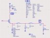
The file "buck" details the used buck converter which is a basical buck design.
The load is a 50Ω resistor.

I would want to switch this buck with an appropriate gate driver, what kind of gate driver I need?

Thank you in advance.
 

Attachments

  • buck.jpg
    buck.jpg
    68.1 KB · Views: 373
Hello,

Finally I decided to use a low side driver, it is faster than high side ICs.

But between the buck converter and this driver (EL7457) I need to introduce a level shifting circuit!

Could you give me idea to create a level shifting circuit?
 

Attachments

  • Datasheet fn7288.pdf
    638.5 KB · Views: 428
that's not a MOSFET driver. If it were, you would not want to use it to drive the upper MOSFET. Can I ask how you decided on the 1MHz switching frequency? What is the load current? What is the output voltage?
 
I want to get a switching frequency as high as possible, :) but if I can reach the 1 MHz, I will be happy.

The load current is expected to move between 500mA to 2A maximum.
The output voltage : 20V to 65V.
 
Why do you have two coils in line with each other? Both of them are too large for 1Mhz switching speed at 2A output. Switching speed, inductance of the main coil, and max output current are directly dependent on each other. I would go with 100-200Khz max on the switching speed. Will make it much easier to find inductors that handle 2A.

Typically, unless you use logic level mosfets, you need two voltage supplies to run a switching system. One at 3.3-5.0V for the control circuitry and one at 10-12V for the power circuitry (mosfet drivers and mosfets).

You're also going to need a different mosfet, as this one is only rated for 80V. You should make sure it's rated for double the input voltage to be safe. It also does not have enough current rating for 2.0A output. It's going to need to be rated for about 10A or so for a 2.0A continuous output.
 
Thank you for these informations.

@blueroomelectronics : this buck will be a part of an envelope amplifier able to follow the envelope of a RF signal.

@Smanches : I post a picture showing simulation result of this buck which is driven by a pulsed signal at 1MHz.
Maybe I m wrong but it seems according to the simulation that the output switches at 1MHz.
About the 2 coils, it's a low pass filter, with a cut off frequency higher than expected Fs.

OutToLunch tolme that the driver I m using is not a MOSFET driver! that means I have to remove all components I m using, °_°
 

Attachments

  • graph.jpg
    graph.jpg
    49.3 KB · Views: 194
Last edited:
I think you need to read up on buck regulators. First, the output filter - which would consist only of L5 and C5 should have the double pole WELL BELOW the switching frequency - not above it. You want to filter out the switching and create a DC output. L4 should not be there at all. A single 1pF output capacitor on a buck is pretty much like not even having one there. You need capacitance at least in the 10s of uFs. The switching frequency of the regulator does not need to be so high - you're creating a DC supply and even if you had fast transients, which I highly doubt, these could be dealt with at 200-300kHz very easily.

Your choice of FET drivers is the least of your problems right now.
 
Thank you for this explanation.:eek: It seems very complicate to design a basic buck converter.
Ok L4 is useless and my buck is wrong, but why the simulating circuit provides quite good result?
 
The results of your simulation were not good. The objective is to create a DC voltage on the output and your results showed an output switching from 0V to 70V. The output was just a recreation of the voltage at the source of the FET - that switching voltage is supposed to be filtered out by the LC filter.
 
Ok
After a long time looking for buck regulator design informations, I really don't find information which clearly gives L=... and C=... according to requirements.


I just find this tool :
Switching Converter Power Supply Calculator

With this tool I obtained L & C values and a DC voltage across the load :
Is this better?
 

Attachments

  • new.jpg
    new.jpg
    46.5 KB · Views: 150
Last edited:
Yes the calculator works for the most part, but it's not doing the caps right for a buck. Maximum voltage ripple is at minimum duty cycle, and it's calculating the cap for maximum duty cycle which isn't going to help at all.

Minimum duty cycle in this case is the lowest duty cycle you can go and still have acceptable voltage ripple on the output, which you have to determine by your needs.

Otherwise the numbers look right. Just make sure you always put in the worst-case figures.
 
Ok thank you for these informations. Yes in a way this is what I want to do, but the signal of few MHz is a low frequency signal compared to RF.
 
Because, I need very high level of efficiency, >80%. You don't have RF amp working at such level. The power I need is around 130W.
 
I seem to be missing something here...:(

Whats the conection between a buck convertor power supply and an RF amp...surely the two are completely different in what they do?
 
Status
Not open for further replies.

Latest threads

New Articles From Microcontroller Tips

Back
Top