Continue to Site

Welcome to our site!

Electro Tech is an online community (with over 170,000 members) who enjoy talking about and building electronic circuits, projects and gadgets. To participate you need to register. Registration is free. Click here to register now.

  • Welcome to our site! Electro Tech is an online community (with over 170,000 members) who enjoy talking about and building electronic circuits, projects and gadgets. To participate you need to register. Registration is free. Click here to register now.

How to determine current limiting resistor for a random LED?

Status
Not open for further replies.
What is the correct way to determine the current limiting resistor for a random LED that you pulled from your stock pile? You have no idea the manufacturer, part number, current requirement, or voltage drop. How does one determine the size of the resistor?
 
I'd start by looking at online images to see if I could find one of the same appearance and dimensions, then look up the spec for that to establish its likely max continuous current and typical Vf. Divide the max current by 2 to give a good safety margin. Use Ohm's law to determine R from that current value and knowing Vsupply-Vf. It's NOT a foolproof method ;).
 
As an example, I have a drawer of T1 3/4 green and red LEDs that I have acquired (new) over the years. Last night I blew out two before I was able to reduce the current to what they required. After I increased the resistor and replaced the diode for the second time, it barely lit. I then reduced the resistor back to what it was and it looks good now. So I must have two different max current LEDs in the drawer. My initial target current was about 5mA (5V and 4.7K). That blow out the first two but worked with the third. I knew something was wrong with the first one as it was way too bright, but could not get it shut off before the LED died.

I'm not sure looking for something that looks physically similar is going to work. Is there a way to determine Vf for the diode? DVM with diode setting?
 
I'm not sure looking for something that looks physically similar is going to work.
Possibly not, but that should weed out obvious mis-fits.
Suck it and see with the DVM. Nothing to lose. May or may not work depending on meter brand/features.
 
Get yourself something similar to the following: (I'm not endorsing this particular seller, there are many and this is only used as an illustration)

**broken link removed**

For US$2.23 and free shipping, it should be in everyone's bench who uses lots of leds.

It has enabled me to purchase led "grab bags", and on a lazy afternoon I can sort them by color and brightness. And discard the defective ones.
 
If you have a variable DC supply just put about a 500 ohm resistor is series with the LED and increase the voltage until it's reasonable bright.
Alternately use a 2k pot connected as a rheostat in series with a 500 ohm resistor and the LED.
That should give a good operating current which you can determine from the voltage drop across the resistor.
You can also then measure the diode drop to use in calculating the proper resistance value for the intended operating voltage.

I was trying not to lead the horse to water. I wanted to see if there where any better ideas out there. That is the direction I was thinking. Connect the pot between PS+ and LED anode. With the LED cathode connected to ground, measuring the voltage at the cathode is the diode drop. But from the diode drop, how do I determine what current I should be running the LED at?
 
The diode drop is used only as part of the calculation for the correct resistor sized based upon the supply voltage and the desired LED current.
The current is determined by observing the brightness of the LED. The brightness will increase with current until it starts to level off.
Operate with a current some below that point or at the desired brightness.
Most small LEDs are rated at 20mA.
 
Looks like the ones I have aren't in the 'most' category. I understand what you are saying. Once I have the Vf, recalculate R based on the actual circuit power supply voltage. If the voltage of the end circuit is different, then the required resistor will be different.
 
As an example, I have a drawer of T1 3/4 green and red LEDs that I have acquired (new) over the years. Last night I blew out two before I was able to reduce the current to what they required. After I increased the resistor and replaced the diode for the second time, it barely lit. I then reduced the resistor back to what it was and it looks good now. So I must have two different max current LEDs in the drawer. My initial target current was about 5mA (5V and 4.7K). That blow out the first two but worked with the third. I knew something was wrong with the first one as it was way too bright, but could not get it shut off before the LED died.

What value resistor did you blow the LED's with? - they work over a MASSIVE range - and 4.7K would only produce less than 1mA (the LED should still light even at that though, and would be a good 100% safe value to test with).

I'm not sure looking for something that looks physically similar is going to work. Is there a way to determine Vf for the diode? DVM with diode setting?

A DVM should work fine - but I've never found the Vf at all critical, as long as you're not trying to drive the LED as bright as possible.
 
My bad. First two blew on 5V with 1K thus 5mA. Then I changed to 4.7K (1mA) for LED #3 and the led barely glowed. I changed back to 1k and it looks good.

To the best of my knowledge these are just regular red or green T1 3/4 LEDs, several years old. Nothing fancy (no high output, low power, etc.)...to the best of my knowledge.
 
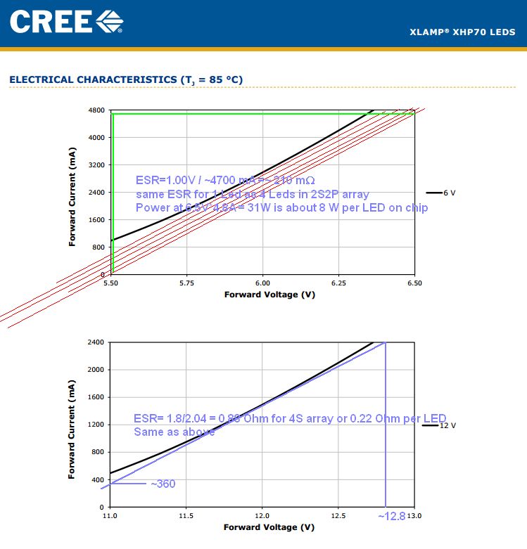
All diodes including LED's have a threshold voltage, Vth ( at say 10% of rated current) , a rated forward voltage Vf @ If and the difference in voltage can be used to approximate the effective series resistance inside or ESR.

Having worked with thousands of different types of LED's, I have a rule of thumb that the ESR of the diode is inversely proportional to the power rating such that the product term is nearly constant across all good vendors and sizes. Poor quality ones will be higher ESR per Watt or higher Vf per Amp unless in series strings. It also varies with chemistry, process & wavelength and is not exact.

When testing be sure never to exceed 5V as this is the maximum reverse voltage for ALL LEDs. Even though the leakage is only 1uA for Red/Yellow and 10uW for small Blue/White, the current rises rapidly at -10V and the breakdown is catastrophic or wounds it like ESD with infant mortality.

Which brings up another issue ... Handling.
I only buy LED's with zener protection or design them back to back, if handling or stray transient fields are nearby. Of course how you handle them is your problem, since you can never guess which polarity your ESD will be on constant.

Anyhow, my Rule of Thumb is 1 Watt-Ohm (WΩ) for internal ESR which is included in the Ohm's Law curve for V vs I with an external current limiting resistor.

Once you establish ESR, Choosing the resistor is just Ohm's Law between Vth and Vf.
The problem is few understand this so they dont spec Vth only Vf, but you can memorize these values.

Vf is inversely proportional to the wavelength.
For High Bright (HB) LEDs
IR Vth 0.8 Vf=1.0
Red , Yellow Vth=1.8 Vf=2.0-2.3
Blue, White Vth=2.8 Vf=3.0~3.5
UV ....more

The older RED LEDS were a lower Vf due to the longer wavelength.

Epoxy 5mm LEDs are thermally insulated, so the standard is 20 mA .
SMD can much higher with thicker gold μwire bonds and better thermal resistance.
Current ratings are thus according to size & heatsink with large variations unlike epoxy encapsulated ones.

Use a large resistor like 2 or 3K to measure the voltage drop, I call Vth from 5V. ( Not 12 incase you reverse it)
You can extrapolate to Vth if you know the power rating then use Ohm's Law for the difference R that limits current.
4832753300_1424900646.jpg


This is obvious a high powered array of LEDs on a chip. 4S means 4 in series and the upper one 2S2P ,, you can guess. ;)
 
Last edited:
My bad. First two blew on 5V with 1K thus 5mA. Then I changed to 4.7K (1mA) for LED #3 and the led barely glowed. I changed back to 1k and it looks good.

To the best of my knowledge these are just regular red or green T1 3/4 LEDs, several years old. Nothing fancy (no high output, low power, etc.)...to the best of my knowledge.

I can't really see a 1K resistor blowing an LED?, as you say it's only 5mA (and that's in to a short, it will only be 3mA or so to an LED).

Probably those LED's were faulty?
 
Probably blown from ESD. The #1 cause of LED failures.. #2 is excess solder heat duration exceeding 3 seconds at 600F.

In short the user is the #1 cause of failure. ( but they usually fail open ;) or #3 cause , lead bending exceed guidelines.

Do you know how easy it is to generate -10V with ESD > 10uA? thats equivalent to a 1MΩ leakage ESR but blows the jcn with 2x spec for example. The first sign of failure having tested a factory for ESD causes is .. LED still works but causes a phase shift... ( junction closing , rising capacitance) then blows open. In this client's case, they had no less than 6 causes of ESD from , debagging, stuffing and plastic injection molding. Since I supplied with zeners, factory failures stopped. They had 0 failures of unused parts.

Those who logon onto EDAFORUM can see my album of person Luminaire designs around the yard. **broken link removed**
 
Last edited:
initially use a larger supply like 12 V where Vf doesn't matter too much. Colors change Vf. Start out with something that will deliver from about 0.5 mA to 10 mA. If you really want to be careful, use a current source. Simple one resistor programmable ones exist from TI and linear technology.

Monitor brightness and Vf. the diode test MAY be able to register Vf. A reminder that some LEDs have an internal resistor.
 
You can use the forward voltage drop of the LED to gauge its junction temperature rise. Apply a known test current to the LED, starting off at a safe value (say 3 mA). Immediately measure the forward voltage drop of the LED (to millivolt precision) and record it as Va. Wait until the forward voltage drop stabilizes (stops falling) and then record the forward voltage drop as Vb. Calculate the junction temperature rise of the LED at the stabilized state as Tb (deg C) = (Va-Vb)/0.0022. Tb should be no greater than 100 deg C - Ambient Temp at the highest test current. This is an approximation since the tempco of the forward voltage drop varies between different types of LEDs and is not always -2.2mV/degC. More accurate determination can be made by looking up the tempco for the type of LED closest to what you are testing. If you use -1mV/degC you will err on the side of caution for all LEDs.
 
Last edited:
Status
Not open for further replies.

Latest threads

New Articles From Microcontroller Tips

Back
Top