kjennejohn
New Member
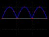
You're welcome. Actually, it has to rise or fall TEN Volts from 230V to trigger. Then it has to get back to within FIVE Volts of 230V in order to turn the relay back on.
I hope this project works to your satisfaction into the future.
kenjj
I hope this project works to your satisfaction into the future.
kenjj
Last edited:


")