Continue to Site

Welcome to our site!

Electro Tech is an online community (with over 170,000 members) who enjoy talking about and building electronic circuits, projects and gadgets. To participate you need to register. Registration is free. Click here to register now.

  • Welcome to our site! Electro Tech is an online community (with over 170,000 members) who enjoy talking about and building electronic circuits, projects and gadgets. To participate you need to register. Registration is free. Click here to register now.

how to Design a counter which counts 0, 4, 8, 2, 6

Status
Not open for further replies.
this is the k-map for the three flip-flops
 

Attachments

  • K-MAPS.png
    K-MAPS.png
    206.1 KB · Views: 480
The JK Map is almost right, well done.

You made a mistake with JD.

Also, you only need 3 Flip Flops. A is just connected to Gnd.

In the attachments you will see that I divided the figures by 2 before drawing the Next State Table & the K maps.

I'll look at the T case later, I have other things to do at the moment.
 

Attachments

  • Next state table.jpg
    Next state table.jpg
    81.9 KB · Views: 534
  • JK Maps LJC.jpg
    JK Maps LJC.jpg
    263.7 KB · Views: 493
I have looked at the T & D cases.

You have made some minor errors, see the attachments.

However, check what I have done, I can make mistakes also.

EDIT
Fixed the error in the third attachment.
 

Attachments

  • TD map LC.jpg
    TD map LC.jpg
    52.1 KB · Views: 435
  • D table LC.png
    D table LC.png
    91.3 KB · Views: 430
  • D Maps LC.jpg
    D Maps LC.jpg
    161.6 KB · Views: 459
Last edited:
i fixed the mistakes

and this is the final results for K-map

now i will start design the first counter and when i finish it i will post it here
 

Attachments

  • K-MAPS1.png
    K-MAPS1.png
    196.1 KB · Views: 408
Your attachment looks good.

The only comment I would make is that you still have A in the Karnaugh Maps.

You don't need a Flip Flop for A.

It is 8:21 pm here now, so I'll have a look at your counters in the morning.
 
ok no problem i will wait until the morning

i done the counters but i think there is some mistakes
 

Attachments

  • JK COUNTER.png
    JK COUNTER.png
    19.2 KB · Views: 401
  • T COUNTER.png
    T COUNTER.png
    34.8 KB · Views: 409
  • D COUNTER.png
    D COUNTER.png
    35.1 KB · Views: 427
Last edited:
I only found one minor error in the JK drawing.

See attachment.
 

Attachments

  • JK COUNTER LC.png
    JK COUNTER LC.png
    20.4 KB · Views: 409
thank you very much

i fix it

now, i want you to help me with the second part
2. Modify your design in question 1.a so that the circuit works according to the following function table
X Y F
0 0 Clear
0 1 No Change
1 0 Parallel Loading
1 1 Count

because i don't have any ideas of the way it done by it
 
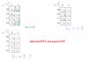
I have attached the data sheet for the 4027 Dual JK Flip Flop IC.

Motorola call it the MC14027, other manufacturers use other prefixes such as CD4027, etc.

Note that the 4027 has Set (S) and Reset (R) inputs. These are called asynschonous inputs since they are independent of the clock. Some manufacturers call them Preset & Clear.

The J & K are called synchronous inputs as they are dependent upon the clock.

Look at the general description, Truth Table & the Block Diagram on page 1.

The Truth Table defines how the FF behaves under the various input stimuli.

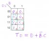
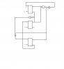
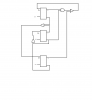
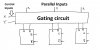
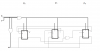
You will need gating to control the functions. The inputs will be X & Y.

The outputs of the gating will go to the S & R inputs. You may also have to design some way of preventing synchronous changes when you want to make asynchronous ones.

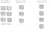
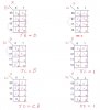
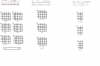
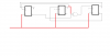
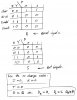
The first step is to draw Karnaugh maps for the S & R inputs. I suggest you forget about the issue in red above initially until you have seen my next post. It is a side issue at this stage.

I will post another attachment later that will help you understand what you're trying to do.
 

Attachments

  • MC14027.pdf
    108.7 KB · Views: 491
Last edited:
I could not find a suitable counter data sheet that was relevant to your needs.

So I have drawn the basic block diagram of what you have to do.

I suggest that you concentrate on the Parallel Load & Clear (Reset) functions first.

Then we can think about the Count & No Change functions.
 

Attachments

  • Set Reset outline.jpg
    Set Reset outline.jpg
    132.6 KB · Views: 410
I think i have done all the cases except the parallel loads


* I have only 20 hours to finish it and i think it's not enough time
 

Attachments

  • JK COUNTER.png
    JK COUNTER.png
    24.4 KB · Views: 404
The logic is wrong in your drawing.

Since you are running out of time, I have drawn the Karnaugh maps for the Set & Reset inputs to the Flip Flops and have given you a clue as to how to do the "No change" case.
 

Attachments

  • Control Logic.jpg
    Control Logic.jpg
    266.1 KB · Views: 400
i don't understand the k-maps
and how to do the parallel load

The logic is as follows:-
To Clear all FF, ie. when X = 0 & Y = 0, you apply 1 to all R inputs.

To parallel Load, ie. when X = 1 & Y = 1, you make S = 1 & R = 0 if P = 1 or if P = 0 then you make S = 0 & R = 1.

Where P is the parallel data to be entered.
 
Last edited:
The logic is as follows:-
To Clear all FF, ie. when X = 0 & Y = 0, you apply 1 to all R inputs.

To parallel Load, ie. when X = 1 & Y = 1, you make S = 1 & R = 0 if P = 1 or if P = 0 then you make S = 0 & R = 1.

Where P is the parallel data to be entered.

where?
we don't learn about parallel load in the class and in the text book it's complicated
so help me please !!!
 
Parallel Load means that you set the counter according to data applied to the Parallel Inputs.

So, for example, if you applied say 110 to the P inputs, then set X = Y = 1, then the counter would be set to 110.

Then if you set X = 1 & Y = 0, the count will start at 110.
 
Last edited:
I finish it and send it to my teacher mybe there are some mistakes .

I just want to say thank you very much for help me without you i never can do it

I grateful to you.
 
You are most welcome.

It is nice to be appreciated, some people don't bother.

Good luck with your studies.

Please let me know what your teacher's comments were on the assignment.
 
Status
Not open for further replies.

Latest threads

New Articles From Microcontroller Tips

Back
Top