Continue to Site

Welcome to our site!

Electro Tech is an online community (with over 170,000 members) who enjoy talking about and building electronic circuits, projects and gadgets. To participate you need to register. Registration is free. Click here to register now.

  • Welcome to our site! Electro Tech is an online community (with over 170,000 members) who enjoy talking about and building electronic circuits, projects and gadgets. To participate you need to register. Registration is free. Click here to register now.

How to daisy chain solenoids

Status
Not open for further replies.

Peterold

New Member
I'm building a backyard aquaponics system that has 4 beds that flood and drain one after the other continuously. I'm controlling it with an arduino, but I'd like to daisy chain the solenoids together so that they don't rely on the arduino to function. The arduino would then just be responsible for starting and stopping the system and monitoring other signals.
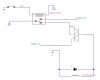
Step by step:
  1. Arduino outputs small voltage to optocoupler
  2. Optocoupler triggers triac -> triac conducts
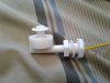
  3. Solenoid opens -> tank fills
  4. Water opens float switch, breaking current flow ->triac stops conducting
  5. Float switch opens -> arduino stops voltage to circuit -> arduino applies voltage to next circuit.
  6. When circuit shuts off, solenoid closes -> tank drains via siphon
    Solenoid Arduino 2017-4-22.JPG
 
Here is how I would do it...
 

Attachments

  • pond_0001.pdf
    307.9 KB · Views: 167
Your polarity is incorrect on the opto isolator input for a positive control signal.
The input LED needs to be forward biased.
There should also be a resistor in series with the opto input to limit the diode current to the desired value.

And for Mike's circuit, the opto transistor collector would go to 12V with the emitter to the 4.7kΩ resistor.
Leave the base connection open.
 
... the opto transistor collector would go to 12V with the emitter to the 4.7kΩ resistor.
...

Since Peter has to tie the Arduino-GND to the 0V-end of the 12V solenoid supply (so that he can sense the state of the solenoid), then why even use an opto-isolator?
 
Since Peter has to tie the Arduino-GND to the 0V-end of the 12V solenoid supply (so that he can sense the state of the solenoid), then why even use an opto-isolator?
Good question.
If he wants to keep things isolated, then he would need to an another opto for the sense signal.

But I don't seen a good reason for requiring isolation.
 
I would run the Arduino on the 12V supply (let the on-board regulator do it's thing). That way, the GND takes care of itself.
 
Hi,
Thanks so much for your advice! I tested the circuit, but unfortunately it's not quite what I need. The solenoid needs to open (filling 1 of the 4 tanks) until the float switch is flipped. Then it closes (and the tank drains completely) until each of the other tanks has flooded and drained. The way it's set up now, the triac is constantly conducting. The triac in Tank(n) needs to stop conducting when the switch opens, trigger Tank(n+1) to fill, and then not conduct again until it is triggered by Tank(n-1).
Sorry for not being more clear.
 

Attachments

  • 20170422_230354.jpg
    20170422_230354.jpg
    370.4 KB · Views: 109
I am still not clear...
Is the Arduino doing the sequencing, or are the solenoids supposed to be autonomously triggering the next in line?
 
The solenoid needs to open (filling 1 of the 4 tanks) until the float switch is flipped. Then it closes (and the tank drains completely) until each of the other tanks has flooded and drained.
I'm still not clear either. Do you want the second tank to start filling (a) when the first tank has just reached the full point and the float switch has flipped, or (b) when the first tank has finished draining? If (b), then you will need some way to sense that draining has finished.
What are the fill and drain times of one tank?
 
I'd like to have the solenoids autonomously trigger the next in line to start filling when the float switch is flipped (tank is full). Fill time is about 15 min and drain time is a bit faster.
 
Does your float switch have both N.O and N.C contacts?
 
It can be either N.O or N.C depending on the orientation.
 

Attachments

  • 20170423_104313.jpg
    20170423_104313.jpg
    1.9 MB · Views: 122
It can be either N.O or N.C depending on the orientation.
I can make an SCR based "ring-counter" which will trigger the solenoids in a "round-robin" fashion where the dwell time in each state is depends on the filling time provided that the float switches are form C (NO and NC, three terminals). If your float switches are only form A or form B, then you will have to add relays with form C contacts that are operated by the existing float switches.

Why does it have to be "autonomous"? Why not just let the Arduino run it?
 
So this is some kind of ring counter or shift register, with a float switch in each tank and a solenoid between each pair of tanks? Since we're more than half-way through this game of 20-posts, how about a diagram of the setup?

ak
 
I'm part of the DIY aquaponics community, and I want to make something that will be versatile for anybody's system and easy to use. I don't want to use a timer because then you have to manually change the timing based on tank size, and you'd have to be pretty precise so you don't have error propagation over time. I want it to work independently from the arduino, so that you could add or subtract tanks without changing the arduino code. It would also remove a fail point if something happened to the arduino. The flooding and draining needs to be as reliable as possible.

I could buy relays. So the relay would be N.C when the tank is filling, then the float switch would flip it to N.O when the tank is full(changing the next tank to N.C), and when the system got back around it would flip back to N.C?
 
If we use one relay per float switch, we can also make the relay latch and eliminate the SCR/TRIAC.
 
If we use one relay per float switch, we can also make the relay latch and eliminate the SCR/TRIAC.
Would something like this work(no latching, w/ triac)?

What you suggested would be better since it's simpler, but I can't figure out how it would work with no triac.
 

Attachments

  • Solenoid Relay 17-04-23.JPG
    Solenoid Relay 17-04-23.JPG
    29.9 KB · Views: 113
The triac or SCR is the "latch". You have to come up with a way of triggering it on (the n-1 tank water level became "full"), and then you have turn it off (the nth tank just became "full").

A ring counter made this way has a lot of hazards. For example, what happens if more than one triac/scr comes on when power is first applied. Will it sort itself out and settle into "only one on at a time" cadence? Not easily.

A ring-counter made from four "latches" is a state-machine with 16 states, only four of which are useful to you, specifically 1000, 0100, 0010, and 0001. It needs an Arduino (or lots of discrete steering logic) to detect the 12 illegal states so as to put it into the legal sequence. This gets more complex than letting the Arduino sort it out...
 
Status
Not open for further replies.

Latest threads

New Articles From Microcontroller Tips

Back
Top