Continue to Site

Welcome to our site!

Electro Tech is an online community (with over 170,000 members) who enjoy talking about and building electronic circuits, projects and gadgets. To participate you need to register. Registration is free. Click here to register now.

  • Welcome to our site! Electro Tech is an online community (with over 170,000 members) who enjoy talking about and building electronic circuits, projects and gadgets. To participate you need to register. Registration is free. Click here to register now.

How to capture both channels of the radio broadcast band?

Status
Not open for further replies.

Hacdrag

Member
I've never built any radios but have put together a few simple Bluetooth speaker circuits. I want to build a simple transistor-based broadcast FM radio. There are many plans and circuit diagrams available online that I can follow, but they are all going to produce mono output. I'm admittedly a "newbie" at most of this but want to know the theory about how to get separate feeds for both channels. Can somebody give me some ideas and/or some diagrams?

If it makes a difference for the answer, I'm going to be sending the output to a small, digital amp module.
 
Look for a stereo FM receiver circuit.
It detects the 19kHz stereo pilot signal and doubles that to 38kHz for use in a demodulator to separate out the left and right channels.
 
Take the output from the FM discriminator.
Use 2 diodes to detect the Modulating signal just like in an AM radio.
The +ve output will be Left Channel, the -ve output the Right Channel.

The FM discriminator output is actually a DSB AM on a carrier of 38 KHz, with the Left and Right channels on the Top and Bottom envelopes of the AM signal.
 
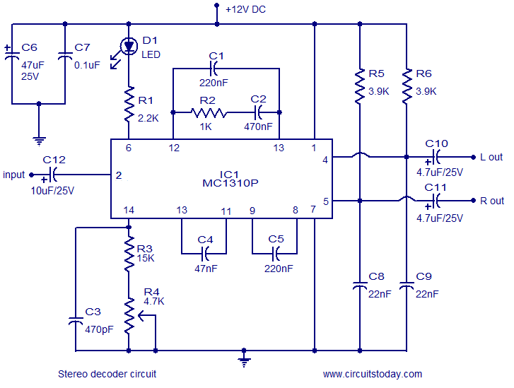
There used to be dozens of different stereo decoder ICs, but most are discontinued.
It looks like there are still a few MC1310 ICs available if you shop around.


Example circuit:

The FM receiver must use a high quality demodulator, not a slope detector, as the stereo "difference" information needed to separate the channels is sent using an ultrasonic carrier, as Crutshaw said.

[And it's nothing to do with the polarity of a demodulator diode..]
 
Take the output from the FM discriminator.
Use 2 diodes to detect the Modulating signal just like in an AM radio.
The +ve output will be Left Channel, the -ve output the Right Channel.

The FM discriminator output is actually a DSB AM on a carrier of 38 KHz, with the Left and Right channels on the Top and Bottom envelopes of the AM signal.
The diodes will not work, as it's not a standard or AM signal.
It's more like a multiplexed signal with the two channels sent on alternate samples at a 38kHz sample rate.
This requires a demodulator that uses the 38kHz clock to separate the alternate samples back into the left and right signals.
 
The diodes will not work, as it's not a standard or AM signal.
It's more like a multiplexed signal with the two channels sent on alternate samples at a 38kHz sample rate.
This requires a demodulator that uses the 38kHz clock to separate the alternate samples back into the left and right signals.
Certainly won't, it was a crazy suggestion - whatever he's on, he ought to share it :D
 
Take the output from the FM discriminator.
Use 2 diodes to detect the Modulating signal just like in an AM radio.
The +ve output will be Left Channel, the -ve output the Right Channel.
No.

Just plain No.

ak
 
Take the output from the FM discriminator.
Use 2 diodes to detect the Modulating signal just like in an AM radio.
The +ve output will be Left Channel, the -ve output the Right Channel.

The FM discriminator output is actually a DSB AM on a carrier of 38 KHz, with the Left and Right channels on the Top and Bottom envelopes of the AM signal.
Absolutely not!
The 50Hz to 15kHz audio is L+R and the 23kHz to 53kHz with suppressed 38kHz carrier AM is L - R. The AM can be demodulated with a diode but there are no positive and negative outputs.
A matrix adds L + R with L - R to get the Left channel and subtracts them to get the right channel.

Newer demodulators "multiplex" the Left and Right channels at a 38kHz rate.
 
It's more like a multiplexed signal with the two channels sent on alternate samples at a 38kHz sample rate.
This requires a demodulator that uses the 38kHz clock to separate the alternate samples back into the left and right signals.
It's not sampled, it is a purely analog system dating back to the late 1950s or early 60s.

The basic audio is the sum of the left and right channels. The analog "difference" is added in on a 38KHz carrier.

When that is demodulated, the original channels can be recreated by taking the sum and the difference of that with the base audio.

[AG just beat me to it..]
 
I made an Eico FM tuner kit in about 1961 and made their stereo adapter kit in about 1962. They used vacuum tubes like the Heathkit amplifier I made. No more clicks and pops from vinyl records but the records produced 15kHz to 20kHz that FM did not.
I replaced everything with an HH Scott FM stereo receiver in 1964. The receiver still works today but its input selector switch is intermittent.
 
Doesn't the original post suggest he wants to transmit stereo instead of mono? Answers so far are for receiving....
 
It's not sampled, it is a purely analog system dating back to the late 1950s or early 60s.
Yes I misspoke, :oops:
It is not a sampled system but uses DSB modulation.

But interestingly you can demodulate a DSB signal by sampling it at the positive or negative peak of the carrier frequency.
 
The thread title says he wats to capture both audio channels. A radio captures signals.
His first sentence says he never built any radios but put together other circuits.
His second sentence says he wats to build a "broadcast FM radio", not a transmitter.
 
The +ve output will be Left Channel, the -ve output the Right Channel.
it doesn't quite work that way. the channels are multiplexed. the diode arrangement you mentioned is usually used to provide an AFC voltage for the local oscillator (which also can drive a tuning meter)
 
To all those who said NO.
Please try it out - it is quite a simple setup.
I have one made in the late 70's, it still works fine today.
 
This method was used in commercial FM receivers. A couple of references:


1651839510171.jpeg


Both use Full Wave detection, I used Half wave.
 
Status
Not open for further replies.

Latest threads

New Articles From Microcontroller Tips

Back
Top