But .1 ohms * 10.942A = 1.09V is 26% of 4.178V
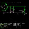
Again 0.05 ohms * 13.658 amps =0.68V which is 32% of 2.166V
32% may not be much at 100 Ohms @ 100V from ESR (assuming I calculated right)
but the percentage rises significantly at high currents.
What I'm going to say is only approximate because the waveshapes involved are not sinusoids, but this should do for a start.
The ripple voltage is due to the voltage drop caused by the ripple current flowing through the impedance of the capacitor. The impedance of the capacitor has two components--the reactance of the capacitor at 100 Hz, and the resistance of the ESR.
For the circuit under discussion here, the reactance of the 2000 uF cap at 100 Hz is .7958 ohms, and the ESR is .1 ohm. They are in series, so the ripple voltage is the sum of the voltage drops across the reactance of the cap (.7958 ohms) and the ESR (.1 ohms). Since the reactance is 8 times as large as the ESR one might think that the voltage across the reactance would be 8 times larger than the voltage across the ESR,
and this would be true if the voltages added arithmetically. But they don't add arithmetically, they add vectorially (if the ripple current were a perfect sinusoid, and approximately so in the real case).
The voltage drop across the perfect 2000 uF cap in series with the .1 ohm ESR would only increase about .8% because those voltages don't add arithmetically; they add vectorially: Vtotal = sqrt(Vcap^2 + Vesr^2).
The reactance of the 2000 uF cap at 100 Hz is .7958 ohms, with ESR=0 (this is also the impedance of the cap with ESR = 0). If the ESR is .1 ohms, then the impedance of the cap is .802 ohms, less than a 1% increase due to the ESR of .1 ohm,
not a 12.5% increase.
The ripple current isn't a perfect sinusoid, so the increase in ripple voltage is more than .8%. To find out what it really is requires solving the non-linear rectifier circuit, which is what a simulation does. The simulation shows that the voltage across the ESR is only about 4% of the total P-P ripple voltage.
Furthermore, you are making a false assumption when you say "
32% may not be much at 100 Ohms @ 100V from ESR (assuming I calculated right) but the percentage rises significantly at high currents."
This would be true if the voltage across the reactance of the capacitor remained the same as at lower currents. But the ripple current flows through the capacitor's reactance in series with the ESR. The voltage across the reactance goes up in the same proportion as the voltage across the ESR. Therefore, the percentage of the ripple voltage due to the ESR remains the same at all currents.
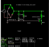
Also, you'll notice that the simulation with the 2000 uF cap showed that with ESR=0, the P-P ripple voltage was 4.279 volts, and with ESR=.1 ohm, the P-P ripple voltage was 4.178 volts.
The ripple voltage decreased with the addition of .1 ohms of ESR, because the increased impedance of the capacitor due to the non-zero ESR reduced the ripple current enough to more than compensate for the extra ripple voltage drop across the ESR.
So, all other things being equal, increased ESR doesn't necessarily increase ripple voltage, and when it does, it doesn't increase it much.
")