MrAl,
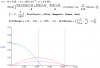
OK, I had a chance to look things over again, and I believe I can show you that for practical purposes, the delay time of the capacitor de-energizing from its maximum value doesn't count for much when compared to the vagaries of capacitor values, which can be ±30% for electrolytics. I used the same example I did in post #32, with a time constant of 20 msec. I show the curve magnified below so it is easy to observe when things happen.
As you can see, the capacitor starts de-energizing at 0.0084 ms. The total period of the 60 Hz wave is 16.667 ms. So, for this example, the capacitor starts de-energizing later at 5% of the period. If the time-constant is higher, the delay time will be less.
View attachment 93124
Ratch
Hello again,
For your first paragraph:
I thought we agreed that we would look at the theoretical aspects only with ideal conditions and components. If you want to allow variations in the capacitor now that means anything we do would be moot. 100us wont matter much over a 16.7ms period, being less than 1 percent of that period. If we stick to the ideal components, then we have something to offer, which i dont see covered in any text, although it should be because any technician can easily see this phenomenon on the scope and wonder why there is a 'hump' at every start of every rectifier output, including full wave rectifier circuits. So if we start allowing component variations then we wont have much to talk about because almost any variation of any kind will swamp any ideal theoretical results we can come up with
")
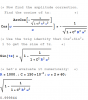
For your second paragraph:
That looks interesting and probably more in line with what we had been talking about all along. I see the blue line looks like the start of a cosine wave, but i dont know what that gold line is...what exactly is that line ? Is that straight or something else, and how did you come up with that line? I ask because the simultaneous solution might be another answer to the smaller time delay question.