Continue to Site

Welcome to our site!

Electro Tech is an online community (with over 170,000 members) who enjoy talking about and building electronic circuits, projects and gadgets. To participate you need to register. Registration is free. Click here to register now.

  • Welcome to our site! Electro Tech is an online community (with over 170,000 members) who enjoy talking about and building electronic circuits, projects and gadgets. To participate you need to register. Registration is free. Click here to register now.

How to balance Milwaukee M18 tool batteries

HR19

Member
Hi there. Some lithium tool batteries have a tendency to go out of balance over long periods, such as Milwaukee's notorious HD 9.0 and 12.0 batteries (the ones I have). They don't have built in cell balancing (even though they have hardware for it), so I'm trying to think about ways to add it. I've seen some people add balance leads for an external balance charger, but I'd rather find a way to add internal balancing so I can keep using my Milwaukee chargers. However I haven't found any balancing boards that are quite small enough to fit inside the existing case. So first question is: does anyone know of any very small (even if very low current and passive) balance boards? Like 15mmx20mm or smaller, and thin. If not, my other idea is to design one using 4.1V zener diodes with 10ohm resistors to create a sort of pseudo-balance board so as they charge up, if they're out of balance, the highest ones will slowly drain to allow the lower ones to catch up. Should this theoretically work the way I am expecting, or am I missing something about circuit design? Thanks!

Also if there happens to be anyone with experience designing circuit boards who's willing to help me design one like what I just mentioned with the diodes, that would be super cool.
 
Do you have any photos of the battery internals and the PCBs in them?

I've never used Milwaukee stuff. I just searched for those batteries & immediately found mention of problems, places banning them due to fires etc.

One comment was someone transplanting the protection board from a 5AH into a 9AH.

I also found a listing for them, stating they have individual cell monitoring. Sounds like some production site really messed up!

 
Hi there. Some lithium tool batteries have a tendency to go out of balance over long periods, such as Milwaukee's notorious HD 9.0 and 12.0 batteries (the ones I have). They don't have built in cell balancing (even though they have hardware for it), so I'm trying to think about ways to add it. I've seen some people add balance leads for an external balance charger, but I'd rather find a way to add internal balancing so I can keep using my Milwaukee chargers. However I haven't found any balancing boards that are quite small enough to fit inside the existing case. So first question is: does anyone know of any very small (even if very low current and passive) balance boards? Like 15mmx20mm or smaller, and thin. If not, my other idea is to design one using 4.1V zener diodes with 10ohm resistors to create a sort of pseudo-balance board so as they charge up, if they're out of balance, the highest ones will slowly drain to allow the lower ones to catch up. Should this theoretically work the way I am expecting, or am I missing something about circuit design? Thanks!

Also if there happens to be anyone with experience designing circuit boards who's willing to help me design one like what I just mentioned with the diodes, that would be super cool.
You can design such a circuit. Pick a compact SMD Zener diode (4.1V, like the BZT52C4V1 or MMSZ series).
Use 10Ω, 0.25–0.5W resistor.
Lay out a compact 5S or 15S board, depending on pack configuration.
Consider daisy-chaining the balancing modules in a thin PCB strip to fit alongside or between cells.
 
Do you have any photos of the battery internals and the PCBs in them?

I've never used Milwaukee stuff. I just searched for those batteries & immediately found mention of problems, places banning them due to fires etc.

One comment was someone transplanting the protection board from a 5AH into a 9AH.

I also found a listing for them, stating they have individual cell monitoring. Sounds like some production site really messed up!

They do have cell monitoring but I want balancing so I don't have to open them up to re-balance if/when they get out of balance again.
 
You can design such a circuit. Pick a compact SMD Zener diode (4.1V, like the BZT52C4V1 or MMSZ series).
Use 10Ω, 0.25–0.5W resistor.
Lay out a compact 5S or 15S board, depending on pack configuration.
Consider daisy-chaining the balancing modules in a thin PCB strip to fit alongside or between cells.
I was wondering if that would work, thanks. I can't seem to find the specific BZT52C4V1 or a 4.1V in the MMSZ series. I did find some axial diodes that are 4.1V and have a relatively tight tolerance, listed as 4.0-4.2V. But it seems like 3.9 is the highest under 4 that comes in tight tolerance. Maybe a tight 3.6+ a 1N4001 or comparable to make a tight 4.1V is the best option. Either that or purchase a large bundle of Zeners and test their actual voltages before assembly.
 
They do have cell monitoring but I want balancing so I don't have to open them up to re-balance if/when they get out of balance again.
Yes, understood - but apparently some versions in that series do have balancing, so the question is about the details of the internal circuit board - does it already have space for the extra components?

If not, a "drop-in" replacement board could be made - with adequate info of what is presently in the battery packs!
 
Zeners must be able to shunt all the power pumped into each cell, so I suspect your Zener solution will burn up.

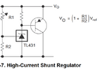
Tell us the max power under CC at say 4V. I would use something more accurate like a TL431 and a power resistor on the PNP collector to dissipate the power outside and place on the bottom. This will a ribbon cable inside or magnet wires to drive the power resistors at 3V at max CC. Chose >>2x power rating to cut the temp rise to 125'C << 50%.


1749447506200.png
 

Attachments

  • 1749447017814.png
    1749447017814.png
    37.9 KB · Views: 47
Yes, understood - but apparently some versions in that series do have balancing, so the question is about the details of the internal circuit board - does it already have space for the extra components?

If not, a "drop-in" replacement board could be made - with adequate info of what is presently in the battery packs!
Interesting, all the documentation and experimentation I have seen shows that they have balancing hardware (through a 1k resistor), but that they are not programmed for balancing. There's some great videos like this one from Tool Scientist. I would LOVE a drop-in replacement but I don't have the skill and knowledge to design one that would still be compatible with Milwaukee chargers.

EDIT: here's a video talking about the communication between the charger and battery:
 
Last edited:
Zeners must be able to shunt all the power pumped into each cell, so I suspect your Zener solution will burn up.

Tell us the max power under CC at say 4V. I would use something more accurate like a TL431 and a power resistor on the PNP collector to dissipate the power outside and place on the bottom. This will a ribbon cable inside or magnet wires to drive the power resistors at 3V at max CC. Chose >>2x power rating to cut the temp rise to 125'C << 50%.
Thank you for this simple circuit. But I'm not sure what you mean about the Zener needing to shunt all the power and burning up. My plan was to use a resisitor (probably 10Ohm) to limit current. And since the Milwaukee charger has cell monitoring, it won't let any cell charge over 4.2V (unless there's a major failure). With a 10Ohm resistor that would limit current to 10mA, which should be fine. The battery will often spend days at a time sitting unused. The worse case scenario (barring a major failure of course) would be that they never charge over 4.1 and therefore don't ever get a chance to balance.

Also I'm sorry, I'm not really good with this stuff, so I don't quite understand what you mean with most of the second section, but the maximum current would be I believe 600mA based one my understanding of how they operate.
 

Latest threads

New Articles From Microcontroller Tips

Back
Top