Continue to Site

Welcome to our site!

Electro Tech is an online community (with over 170,000 members) who enjoy talking about and building electronic circuits, projects and gadgets. To participate you need to register. Registration is free. Click here to register now.

  • Welcome to our site! Electro Tech is an online community (with over 170,000 members) who enjoy talking about and building electronic circuits, projects and gadgets. To participate you need to register. Registration is free. Click here to register now.

How Many Amps/Volts Can This Handle?

Status
Not open for further replies.
Switchcraft make very high quality American connectors with detailed spec's, not imported cheap Chinese junk with no spec's.
 
Last edited:
In a nut shell yep, pretty much. The main idea is that it's able to be panel mounted if possible. I'm not sure what a bulkhead connector is, but if it's the type of connector that has both positive/negative leads in one cable, then yes. I mostly do not want to end up with 2 separate cables that have to be plugged in to charge it. I want to use 1 cable that plugs into 1 port and charges the batteries.

A "bulkhead" connector is a box mount or as KISS mentioned a panel mount. Naming conventions are mostly a manufacturer thing. Many connectors are literally built using a part number. Take a lookie here to get an idea of what I am talking about. For example you would want a MS3102A-10SL-4P which is a box mount, two contact, size 10 pin (meaning male side) or a MS3102A-10SL-4S would be the female version of the same box connector. Assuming the power source would go to the box you want the box connector to be female. (P for Pin and S for Socket). The mating connector in a straight plug would be a MS3106A-10SL-4S. The size I mentioned here will accept two AWG 16 wires and use solder cup. I used Amphenol part numbers and Allied Electronics as the source. When building a connector like this, you also need a backshell for the connector which is bought separate. The backshell is the cable clamp section and is bought based on the shell size or #10 for the connectors I mentioned, something like this. Just a m,atter of how fancy you want to get. :)

Connectors become an endless nightmare. As the connector size grows larger pins higher current and the greater the pin spacing the higher the working voltage. You choose a connector based on the application.

Ron
 
Okay, well I received my package in the mail from mouser, however, it was only shipped with the "male" connector and not the "female" side. On the image it showed both as you can see here: https://www.mouser.com/ProductDetai...piMZZMu2f9RNbWupYqW6S1LL%2bTeZ784y6a4ugIw=#AB

I'm not quite sure how to determine from the description if it comes with both or not, but if it doesn't, how can I find the correct female connector as shown in the image?
 
I'll let you do it rather than do it for you.
Click on data sheet.
You'll get a list of mating products.
Search for the mfr p/n of the 3 listed mating parts.
 
If you want a mating connector and want it soon Radio Shack sells the things. If you look at this data sheet and find the part number it goes with Figure A. Switchcraft part number 761KS12. You got what you ordered but I agree the mouser catalog is a little misleading if you don't really follow through with the manufacturer's data sheet.

Ron
 
Okay, I received my components in the mail, however, I need to confirm how to hook my positive/negative connections to them and also how to crimp the terminals.

Attached is a photo, and also a cut out of the L722AS datasheet.

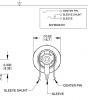
For the L722AS (female end), I'm assuming from the datasheet the "sleeve Shunt and sleeve" are connected together, so if I want that to be my negative connection, I just connect both of those together, and the positive connection to the "center pin" ?

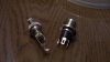
As for the male end, I'm just not 100% how you are suppose to secure your wire you attach to it...either by crimping the metal part or doing something else?

In a nut shell, I just need help figuring out how to hook up the positive/negative wires to these two components properly.
 

Attachments

  • Screen shot 2011-07-13 at 9.46.18 PM.png
    Screen shot 2011-07-13 at 9.46.18 PM.png
    42.5 KB · Views: 141
  • IMG_3056.JPG
    IMG_3056.JPG
    1 MB · Views: 143
I forget (and I frankly don't have the interest at this point to go back and re-read this humungous thread): did you want this connector to switch something in your circuit?

Because if not, then just forget about the "shunt" connector and connect your negative terminal to the sleeve.

If you want something to be disconnected, then use the "shunt" connector as a switch (normally-closed).

Regarding the connector terminals, what you got there, good buddy, are good old solder terminals. Time to fire up your soldering iron. Crimping ain't gonna do it. (You may use that crimp-able tab on the plug sleeve to wrap around the cable to secure it, but you definitely need to solder the wires to the terminals.)
 
Status
Not open for further replies.

Latest threads

New Articles From Microcontroller Tips

Back
Top