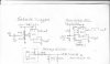
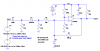
In the circuit that you suggested, what is the purpose of the second diode that is connected from the comparator's '+' input to ground, with the diode's anode connected to the '+' input ? [/FONT]
I was able to use the resultant positive pulses from the differenting ckt, right from the 'top' of R2, apply them directly to my BS2 and derive an appropriate pulse count. Since I'm applying the ignition pulses to a 3:1 voltage divider, the ignition pulses are dropped down to less than 4 volts. Then they are applied to the differntiator/clipper ckt with the resultant positve pulses applied to the BS2. For some reason the diffed. pulses were greatly attenuated at the input to the comparator, and were apparently too small for the comparator to sense. I'm wondering if the second diode has something to do with the sharp attenuation of those pulses. If the diffed. pulses continue to work ok, that might be all I need to use.
The original ignition pulses are 'negative' pulses that drop from the MC's 12v to ground for a few milliseconds then back to 12v, with an approximate frequency range of 17 to 75 pps
thank you
PO'T