Continue to Site

Welcome to our site!

Electro Tech is an online community (with over 170,000 members) who enjoy talking about and building electronic circuits, projects and gadgets. To participate you need to register. Registration is free. Click here to register now.

  • Welcome to our site! Electro Tech is an online community (with over 170,000 members) who enjoy talking about and building electronic circuits, projects and gadgets. To participate you need to register. Registration is free. Click here to register now.

How does my schematic to stripboard layout look? First time

Status
Not open for further replies.
Hey guys I've been working on a project for quite some time with help from people on these forums. My project is to make a sound activated LED light box. What it does is turn the LED lights on and off to the music. (Example of what I want to make:

)

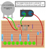
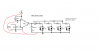
So with the help of people on this forum this is the schematic I ended up with, attached below. Now this is my first time making something with electronics, so I'm still learning. I used a free online program called "DIYLC" to attempt to lay out my stripboard design, since I don't have a breadboard. My layout so far is attached below as well!

I tried my best to interpret the schematic into a stripboard design.
Any help to make my stripboard design actually work would be greatly appreciated, thank you!
 

Attachments

  • led schematic.png
    led schematic.png
    25.2 KB · Views: 404
  • perfboard layout.png
    perfboard layout.png
    138.1 KB · Views: 342
The 10 Ohm resistor is not connected correctly on the perfboard.
You need breaks in the tracks under the IC to avoid pin-to-pin shorts.
The top ends of all the 220 Ohm resistors should connect together (row I) on the perfboard.
The lower terminal of the .047 cap goes nowhere useful on the perfboard.
Presumably the perfboard is transparent as shown? If not, the IC orientation is mirror-image.
 
Putting nearly ZERO effort into looking at your design, the LED's would have a lot of trouble.

Part of the strip board construction method is to cut the strips as required to make smaller paths. I think you totally missed that concept.

Not too crazy about LED's in parallel. I would use a resistor for each LED.

The idea behind "color organ" is to split the audio into frequency bands and activate the different color based on audio amplitude. Now, you could do an ersatz design that I did some 30 years ago ---> Blinking xmas lights (the very large ones) in a speaker-like enclosure with a standard florescent light plastic cover. No music required.:)
 
The 10 Ohm resistor is not connected correctly on the perfboard.
You need breaks in the tracks under the IC to avoid pin-to-pin shorts.
The top ends of all the 220 Ohm resistors should connect together (row I) on the perfboard.
The lower terminal of the .047 cap goes nowhere useful on the perfboard.
Presumably the perfboard is transparent as shown? If not, the IC orientation is mirror-image.

Switched placement of the 10ohm resistor.
I had breaks under the IC but I made the IC transparent so you can see it now.
I made all the top ends of the 220 ohm resistors to row J while extended the capacitor to row J as well.

How does it look now?
 

Attachments

  • stripboard layout.png
    stripboard layout.png
    139.3 KB · Views: 363
How does it look now?
That's more like it! I see the LEDs are in series on the board, which is better than the parallel arrangement in the schematic.
 
I see the LEDs are in series on the board, which is better than the parallel arrangement in the schematic.
In the schematic, the LEDs are wired in "anti-parallel", in other words thay are parallel connected with opposite polarity, which is what is required for the AC output of the amplifier. The LEDs will illuninate on both halves of the waveform.
If they are wired in series, they will need more voltage to illuminate.

JimB
 
You're right, Jim. So the stripboard layout needs correcting to put the LEDs in anti-parallel.
 
You show stripboard, not perfboard. The strips of copper are easily cut with a drill bit at a vacant hole, not between holes which you show.
You show the top view of the IC so the strips are cut in a mirror image on the other side. The parts and some jumper wires are on the side without copper. The copper strips, cut strips and solder are on the other side.

You have the LEDs in series instead of back-to-back like on the schematic and you have the LEDs shorted by strips of copper on the circuit board.
I agree that the 10 ohm resistor is in the wrong place. It should connect from the 0.047uF capacitor directly to pin 4 of the IC.
I agree that there should be 4 cuts under the IC so that pin 1 does not short to pin 8, pin 2 does not short to pin 7 etc.

The copper strips at pin 1 and pin 8 should be cut so that the entire copper strip is not a transmitting or receiving antenna.
The volume control should be logarithmic (audio taper) not linear.

I realize that you break the connections at the hole, not in between, but that was the only way to break a connection using this program.
I know that everything is on the other side and the copper side is where you cut strips and solder, but again, this is how the program works.

To make the LEDs like the schematic do I just flip the second LED from each section 180 degrees?
How are they being shorted?

For the 10 ohm resistor I don't know if you're talking about the original attachment or the new one, but if the new one, then where should it go?

I'm assuming you didn't look at the newer version because I made the cuts under the IC.

Attached is an even newer version, let me know how it looks, thanks!
 

Attachments

  • stripboard layout2.png
    stripboard layout2.png
    141.2 KB · Views: 379
You still don't have the LEDs in anti-parallel. Each LED should have one leg going to the 220 Ohm resistor and the other leg going to ground.
 
The LED should straddle two strips. i.e. Rotate by 90 degrees.

If there was an imaginary cut under the LED's, they would not complete a circuit.
 
I have one comment: (I did not look it over too well). Unless you bought some really jumbo LED's (which you could have), the normal spacing is 0.1 " or a strip board hole distance.
 
Your LEDs and electrolytic capacitors do not show their polarity.

As I said in post #9, you should cut the copper traces at pin 1 and pin 8 so that the traces are not transmitting or receiving antennas.
I show it as "X" on this layout:
 

Attachments

  • LM386 driving LEDs.png
    LM386 driving LEDs.png
    58.4 KB · Views: 265
Your LEDs and electrolytic capacitors do not show their polarity.

As I said in post #9, you should cut the copper traces at pin 1 and pin 8 so that the traces are not transmitting or receiving antennas.
I show it as "X" on this layout:
What do you mean they don't show their polarity? Like the anode and cathode?
Also, I will break the copper strips for pins 1 and 8, how come though? Just curious about that.
Lastly, do the connections look right at least?
 
Strip 'O' should have some breaks so that each 220Ω feeds a respective anti-parallel pair of LEDs.
 
More comments:

When you actually construct the device, move the POT to the edge of the board. Very easy with what you have drawn.

Do, the same with the power: Use a jumper and bring the negative so it's closer to the positive.

I once got a comment as to why wiring has to be neat when wiring control panels? The chemical engineer thought I was wasting time making it neat.
 
Strip 'O' should have some breaks so that each 220Ω feeds a respective anti-parallel pair of LEDs.
More comments:

When you actually construct the device, move the POT to the edge of the board. Very easy with what you have drawn.

Do, the same with the power: Use a jumper and bring the negative so it's closer to the positive.

I once got a comment as to why wiring has to be neat when wiring control panels? The chemical engineer thought I was wasting time making it neat.
I tried to understand what you guys were saying, hows this look now?
 

Attachments

  • 6.png
    6.png
    129.3 KB · Views: 254
Status
Not open for further replies.

Latest threads

New Articles From Microcontroller Tips

Back
Top