Continue to Site

Welcome to our site!

Electro Tech is an online community (with over 170,000 members) who enjoy talking about and building electronic circuits, projects and gadgets. To participate you need to register. Registration is free. Click here to register now.

  • Welcome to our site! Electro Tech is an online community (with over 170,000 members) who enjoy talking about and building electronic circuits, projects and gadgets. To participate you need to register. Registration is free. Click here to register now.

How does a transistor amplify current or voltage?

Status
Not open for further replies.
Claude,

So the one point Ratchit will not concede is that the Shockley diode equation as follows is fully reciprocating:

Id = Is*exp((Vd/Vt)-1) & Vd = Vt*ln((Id/Is)+1).

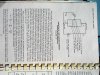
Does the Vd "control" the Id, or vice-versa? It has been correctly stated by almost everyone here that it is a reciprocating, or circular relation. This is so easily verifiable, please refer to the attached SMPS schematic for illustration.

It is a buck converter, where U1 is the control IC. U1 provides the PWM gate drive pulse to switch MOSFET Q1 on/off. When switched on energy builds up in the inductor L1, & this current in the inductor provides output to the load, not shown. The node labeled "+10V" is the output.

While the FET Q1 is ON, the input power supply, "V_IGN" is across diode D1. D1 is reverse biased so that it conducts only reverse leakage current. Here, the V_IGN input is a constant voltage source, CVS, connected across D1 in reverse. The diode current Id, in this case, is determined by diode voltage Vd. So we have

Id = Is*exp((Vd/Vt)-1). As temp varies so will Id, but it is Vd & temp that determine Id.

But the FET Q1 is then turned OFF by U1. The free wheeling inductor current continues through diode D1. In this scenario, the current, Id, is the inductor current at the moment the FET Q1 turned off. An inductor is a current source. L1 will output any & whatever voltage needed to maintain its present value of current. What is the current, Id in D1? It is the current in L1.

Now, what is the voltage, Vd, across D1. To find Vd, we must compute per:

Vd = Vt*ln((Id/Is)+1).

So Vd is determined by Id & temp. Any person experienced w/ SMPS, motors & their drives, induction heating, power generation, antenna, waveguides, transmission lines, etc. is all too familiar with what I've just stated. What I just said is a day at the office for a skilled seasoned EE practitioner. Id is the driving function, & Vd is a consequence, at least during the time L1 de-energizes.

So which is the dog & the tail can be either. It is a fully reciprocating relation. Another example is a simple op amp. The 1st stage is an emitter coupled differential stage. It's output is a current source, as the output current is sourced/sinked by the collector of a bjt in the diff pair. This 1st stage output feeds the 2nd stage input, colloquially named "voltage amplification stage", when it is actually a transimpedance stage (current in - voltage out).

The input stimulus for the npn bjt in the 2nd stage, common emitter topology, is the constant current source outputted by the 1st stage bjt collector. The said current feeds the base terminal of the 2nd stage bjt common emitter. In this case, the base current Ib is the forcing or driving function. When the signal at the 1st stage input increases, due to singing Sue, the 1st stage collector outputs increased current. This results in increased base current to the 2nd stage bjt. The 2nd stage bjt b-e voltage, Vbe, is determined by its Ib value.

So for the 2nd stage bjt, Ic is determined exactly by Ib, per Ic = beta*Ib. Then Vbe is determined by the same junction relation for the SMPS diode above, i.e. proportional to the log of current. Vbe = Vt*ln((beta+1)*Ib)/Ies)+1), or Vbe = Vt*ln((Ie/Ies)+1).

The only issue with this op amp topology is that the open loop gain is beta dependent. At high temp, the beta is greater than at low temp. Also, beta varies from one device to the next. So, the open loop op amp gain is not a precise predictable constant, but variable. But op amps are not run open loop, except in low speed comparator applications, so the gain variation is mitigated through the use of feedback.

Again, Ib, Vbe, & Ie have a circular or reciprocal relation. We can easily, & often do, set Ib or Ie to a specific value, then Vbe becomes a consequence. In the forward direction, a p-n junction is always current driven, because voltage driven forward p-n junctions can easily go into thermal runaway.

In the reverse direction, e.g. the free wheeling diode D1 above, a p-n junction can be voltage driven. But a bjt b-e jcn operates from 0 to around 0.7V Vbe, & negative values are seldom emplyed. So b-e jcns must be current driven. Vbe is a consequence of current, either Ib or Ie.
I agree with the above paragraph except Vbe being a consequence of current. I think it is the other way around. Yes, Ic and Vbe are reciprocals of each other, but as I related to Brownout, no one tries to use Ic to control Vbe. They have a tight relationship to each other, but I consider Vbe controlling Ic, not the other way around.

What I just presented has been common knowledge for a very long time. No revelations here, just going back to basics. A small few people claim that the whole semicon OEM community, the unis, EE practitioners, etc. just don't get it , & that Ib/Ie are mere consequences of Vbe which is the "engine". But the laws of science, evident in common tried & true netorks Like SMPS & op amps, completely refute the notion that "Vbe is the engine, Ib/Ie are just consequences". Ib/Vbe/Ie are mutually inclusive trio. But only 1 can be the quantity directly controlled. The other 2 are indirect. All bjt networks use either Ie, or Ib as the direct quantity, with the other 2 indirect, or incidental. Vbe is never "the engine". The only way Vbe could be the direct control quantity is to connect a very low impedance CVS across b-e jcn. There, the Vbe value literally controls Ib/Ie/Ic. But if you attempt to operate at significant levels of power, your bjt will become a pile of ashes.
I disagree about Vbe not being the controlling factor.

Ratch
 
Brownout,

Reciprocity proves that current is a control agent. Many designs use current to control vbe (ie: integrated logarithmic amplifiers). To say otherwise shows your lack of knowledge and/or experience.
No, it proves they have a one to one relationship to each other. It does not prove which one is in control.

S&S is an introduction to electronics, not semi phy. They only cover the basics. Read a text on semi physics for a change.
The basics still have to match with the advanced.

That's why you need the theory. We've given it to you, but you don't want to deal with reality
You also interpreted it.

We've treated the engineering and the theoretical questions. We are engineers, but are schooled on the theory as well, and use it every day. We know what we're talking about.
Except for the one point we are discussing.

And we have submitted extensive proof, and not just cursory comments. I respect their opinions; I respectfully disagree with them.
And I will study your "proof" when I have time. I am pretty busy in the summer. And I do respect you and Claude's presentation even if I don't agree with it. If I have a question, I will ask about it.

Your links are pretty much worthless. No analysis, no theory and no proof. By contrast, we've provided all the missing parts. Anyone can find links to agree with them, that's why we don't use such lazy arguments. We've done the heavy lifting and shown the answer forwards and backwards. I personally don't care if you think it's voltage or the phase of the moon that controls current, but proof for the current theory has been given over and over and over for pages and pages. Unsubstantiated links are nothing in comparison.
It is true that I am relying a lot on the reputation of those the links reference. It makes sense to be whereas Claude's and yours does not. But I will get around to study what both of you have presented and post my conclusions.

Ratch
 
No, it proves they have a one to one relationship to each other. It does not prove which one is in control.

Got nothing to do with 1-1 relationships, that’s completely irrelevant. It proves that control is reciprocal. Denial of the truth doesn't change it.

The basics still have to match with the advanced.

And so it does. Thus, the basic ebers-moll model correctly models current control.

**broken link removed**

You also interpreted it.

Truth doesn't require interpretation.

Except for the one point we are discussing.

That point has been treated many times, by me and others.

And I will study your "proof" when I have time. I am pretty busy in the summer. And I do respect you and Claude's presentation even if I don't agree with it. If I have a question, I will ask about it.

You seem to have enough time to write contrary statements. Only a fool would contradict that which he hasn't the time to study.

It is true that I am relying a lot on the reputation of those the links reference. It makes sense to be whereas Claude's and yours does not. But I will get around to study what both of you have presented and post my conclusions.

You failure to understand the material doesn’t make it wrong.

as I related to Brownout, no one tries to use Ic to control Vbe

It's done all the time. All manners of nonlinear functions are generated by injecting a current into the BJT's emitter, and amplifying the resulting B-E voltage.
 
Last edited:
Brownout,

Got nothing to do with 1-1 relationships, that’s completely irrelevant. It proves that control is reciprocal. Denial of the truth doesn't change it.
Two variables in the same equation? Of course it has a one to one relationship.

And so it does. Thus, the basic ebers-moll model correctly models current control.
No need to flash me a model. I said earlier that a model is good for what, but not why and how.

Truth doesn't require interpretation.
Truth requires the correct intrepretation.

That point has been treated many times, by me and others.
Not to my satisfaction.

You seem to have enough time to write contrary statements. Only a fool would contradict that which he hasn't the time to study.
Writing statements does not take a long time. Understanding what you present does.

You failure to understand the material doesn’t make it wrong.
That will be decided later.

It's done all the time. All manners of nonlinear functions are generated by injecting a current into the BJT's emitter, and amplifying the resulting B-E voltage.
I like the explanation by Kevin Alyward . To wit:

Basics of Bipolar Transistor Operation
1) The base emitter junction is a diode junction.
2) It can be shown that the current in a diode is causally related to the voltage across it. The relation is:
Id = Is.(exp(Vd/Vt) - 1) - (1)
where Vt is KT/q, and Is is a constant dependant on temperature.
This equation dictates that however Vd is achieved, Id through the junction will be related by the above equation.
3) A voltage instigated via the base and emitter of the transistor is, essentially, equal to Vd of (1), therefore the current that exists through such junction must be related by (1).
That is, the Emitter emits charge into the base region of the transistor, due to the application of Vbe.
4) The emitted charge, once in the base experiences the influence of the voltage at the Collector, and as the base is very thin, collects the charge at the collector terminal and thereby prevents most of the charge flow that would over wise attempt to exit out of the base terminal. Some charge does in fact "leak" out of the base, but this is incidental to the notion that the Emitter current is, essentially, a causal function of applied Vbe, via the diode equation. As most of this current is collected by the collector, the collector current may also be said to be a direct casual function of the applied base emitter voltage.

Ratch
 
Two variables in the same equation? Of course it has a one to one relationship.

It's got nothing at all to do with being in the same equation. The fact that the relationship is reciprocal proves that current is a controlling agent, equal to voltage. In devices, the equations are more than just "two variables" They exhibit real physical reciprocity, observable at the device level as well at the atomic one. The fact, as I pointed out before, that the voltage at the junction depends on continuous injection of current proves that current is at least equal as a controlling agent ( a realtionship that does not hold in real voltage devices ). Neither you nor any of your experts every want to deal with this reality.

No need to flash me a model. I said earlier that a model is good for what, but not why and how.

You said the basic matches the advanced. Thus the basic E-M model correctly shows current control. I've already explained why and how.

Truth requires the correct interpretation.

The truth is in the theory that we've given you. All you have to do is learn it.

Not to my satisfaction.

Irrelevant. We've explained the issues completely. You're rejection of reason and logic doesn't change that.

Writing statements does not take a long time. Understanding what you present does.

Then take the time to understand. You're arguing from a position of admitted ignorance.

That will be decided later.

Meaningless statement.

I like the explanation by Kevin Alyward . To wit:

Oh yeah, the worlds' foremost expert on transistors, that nobody ever heard of before, who's greatest achievement was to get an A in a physics class. He should come to ETO, so we can give him a proper education.

If he would deal with the issues we've been dealing with, he might have something to go on. But you'll never hear any expert address anything beyond the rudimentary one-way exponential equations, because it goes against their cult-like belief.
 
Last edited:
Hello again,


I think i see why the side that exclaims, "The bipolar is Vbe controlled", wants to support that idea. If i am right (correct me if not) that side is stating a basic law, more basic than the transistor itself, that we need to establish an electric field before we can get current to flow, so that means that current can not flow until AFTER we apply a voltage to the base emitter. However, can we say that a resistor is voltage controlled just because a change in voltage produces a change in current?

I dont think i can agree with that because that is just a little too basic, and might still be considered too basic and not actually part of the transistor action itself. The transistor action is still based on current, ie the current is what actually causes the Ic action, and to exemplify that fact a little we can look at the Vbe and the Ib and note that there are a number of Vbe values that do not cause any change in Ic, yet there are almost no values of Ib (except extremely low perhaps) that do NOT cause a change in Ic. That in itself seems to imply current control because the current definitely has more of an effect on Ic over the entire range of possible currents while the voltage range is very restricted. In other words, it seems that voltage is an external influence and current is an internal influence and the internal influence is what actually makes the transistor work. It has already been stated more or less that we dont care about the external circuit because that is really part of the app and not really the transistor itself.

It's hard to separate the two though i guess, because the action of the transistor depends on electron and hole flow at the most basic level, but electron flow depends on voltage to some degree.


However however :) we can also say that a very small delta change in Vbe causes a very large delta in Ic, so that implies voltage control.


Brownout: That's interesting about the moving charge idea. Doesnt a moving charge require a voltage drop though? What about a super conducting transistor however, if that ever will exist, that would not require a voltage drop. Nobody could claim voltage control then :)
 
Last edited:
Kevin Aylward's treatise is as follows from Ratchit's post above:

" Basics of Bipolar Transistor Operation
1) The base emitter junction is a diode junction.
2) It can be shown that the current in a diode is causally related to the voltage across it. The relation is:
Id = Is.(exp(Vd/Vt) - 1) - (1)
where Vt is KT/q, and Is is a constant dependant on temperature.
This equation dictates that however Vd is achieved, Id through the junction will be related by the above equation.
3) A voltage instigated via the base and emitter of the transistor is, essentially, equal to Vd of (1), therefore the current that exists through such junction must be related by (1).
That is, the Emitter emits charge into the base region of the transistor, due to the application of Vbe.
4) The emitted charge, once in the base experiences the influence of the voltage at the Collector, and as the base is very thin, collects the charge at the collector terminal and thereby prevents most of the charge flow that would over wise attempt to exit out of the base terminal. Some charge does in fact "leak" out of the base, but this is incidental to the notion that the Emitter current is, essentially, a causal function of applied Vbe, via the diode equation. As most of this current is collected by the collector, the collector current may also be said to be a direct casual function of the applied base emitter voltage."

Note the terms I emphasized in bold print. KA begins by declaring that diode voltage Vd is the cause of diode current Id. He then states that in a similar manner, bjt Ie is caused by Vbe. THen, of course, Ic is achieved via Vcb with Ib being a residue. Ultimately he concludes that Ic is caused by Vbe w/ Ie intermediate.

He assumes the very thing he attempts to "prove". He states that Vbe has more importance than Ie/Ib because Vbe is what he regards as "causal". As I stated before, the b-e & b-c junctions possess capacitance. For a fixed dc bias, & small ac signa, this cap is usually modeled as constant value w/ reasonable accuracy. For large signal operation, Cbe & Cbc are nonlinear, i.e. value changes w/ charge.

In order to change Vbe, currents Ib & Ie must pre-exist Vbe. What poart of "Eli the ice man" is giving you trouble Ratchit? You cannot "apply Vbe". Take a simple singer, mic, cable, & 1 stage bjt preamp. When Sue sings how does Vbe change? The mic diaphragn vibrates due to Sue being the "cause". Current & voltage, i.e. charge, travel through the mic cable. When this charge arrives at the mic preamp bjt b-e terminals, what happens?

COnduction continues. As charges enter base & emitter regions, Ie & Ib increase. The Vbe barrier has already been established with the dc bias circuit. These new added charges have energy imparted to them by Sue. THen as the charges diffuse/drift, they cross the b-e jcn. But since the number of charges, i.e. "current density", is increased, a larger population of charge carriers is stored at each side of the depletion zone. These charges take finite time to recombine - carrier lifetime. This additional accumulation of excess minority charge results in a change in the local E field, depletion width, & ultimately potential Vbe.

So you simply cannot "change Vbe, or apply Vbe" & claim the the change in Ie/Ib is merely "caused by Vbe". The changes in Ib/Ie take place due to Sue & chronologically precede the change in Vbe. Vbe is not "causing" Ib/Ie to change.

In order to change the local E field & depletion width, a source of energy/work is needed. Vbe is not energy. Vbe is energy per unit charge LOST in crossing the junction. How can a bjt's Vbe be the energy source that changes E field, Ib/Ie, depletion width? Vbe is not an active energy source. Only Sue can provide said energy.

The increase in current is due to Sue. The increase in voltage at the mic element is also due to Sue. These increased quantities ultimately result in an increase in Ib/Ie/Ic & Vbe as well. In order to establish 1 specific entity as the cause, it must exist independently of its consequences. Ib/Vbe/Ie/Ic cannot exist independently of each other. Ie/Ib take place earlier in time than Vbe (change). A consequence cannot precede its cause.

But Sue is totally independent of all these quantites. If Sue turns off her mic, her singing still produces energy. She can proagate acoustic pressure waves w/o Ib/Vbe/Ie. Sue is what is causal.

KA makes no attempt to explain how Vbe being the alleged cause of Ie/Ib, can respond to stimulus after Ib/Ie does. If the bjt was really VC, every semicon OEM would already know it. If Vbe was the cause of Ib/Ie, why do the semicon physics texts never mention it? This causal theory cannot withstand even a mild scrutiny. Several years ago I sent KA an email informing him what I just now stated. He never replied, & never printed my email on his site.

KA has no use for peer review, he is only interested in stating his view of the world w/o any debate from anyone. Science does not advance that way. Causality is a mental block some just cannot overcome.
 
Mr. Al,

Brownout: That's interesting about the moving charge idea. Doesnt a moving charge require a voltage drop though? What about a super conducting transistor however, if that ever will exist, that would not require a voltage drop. Nobody could claim voltage control then :)

I appreciate the humor :) I've never studied super conducting transistors, so I don't even know enough to make a good joke about it!
 
hi Claude,
Well stated....:)
KA has no use for peer review, he is only interested in stating his view of the world w/o any debate from anyone. Science does not advance that way. Causality is a mental block some just cannot overcome.
 
Hi again,


Super conducting transistor: current controlled current source :)

I was going to say that if we can find a mode of bipolar operation where we can get it to operate with Vbe=0, we can prove that it is current controlled.
If we can find a mode of operation where Ibe=0 we can prove voltage control, but i dont see either of these happening soon.

We can of course find a place where delta Vbe is very close to zero, but then it's not exactly zero really.


If we vary Ibe a little we can get Vbe to vary by very very little, if we vary Vbe a little we can get Ibe to vary a lot. The only difference seems to be that there is a different gain associated with each mode of operation.

Maybe we just have to separate what is external and what is internal. I think Vbe is more external to the transistor than current is, therefore current control seems more logical. For example, if the sun is shining into our living room window and it shines on one of the radiators (used to heat the room) and the water heats up and starts to flow via convection currents into a radiator into another room, do we say the system is 'sun' controlled or 'heat' controlled?
We can force that same heat to flow by heating the radiator with a very high power light source, so do we say it is 'light' controlled? We can also force the same effect by using a blow torch to heat the radiator, so do we say it is 'flame' controlled? I believe it can only be called 'heat' controlled, because that's the most internal action that causes an effect. The heat causes the convection flow, while we can get that heat to happen using several different methods, and the end result is always the same either way.
If this sounds like a strange analogy, note that we can shine a light onto the base emitter diode and get current to flow through the collector emitter. The photons will force a current to flow, and that is based on quantum physics.
Ah ha! The transistor is photon controlled now! Or do we simply look at the internal effect and see that it is the current that is causing all the change, ie injected electrons.

Once we fall into a given application though i think we have to go with the flow...if we use light to make the change we would start claiming 'light' control, or if with water then water control, or if with mice then mouse wheel control, etc. We tend to bend the terminology toward the external.

Between two points infinitely far apart held at some voltage level there is no current flow.
Between two points infinitesimally close together with some current flowing there is no voltage drop.
For anything else they both exist simultaneously in a system considered to be lumped.
 
Last edited:
Hello again,

Well thank you Brownout. The only thing left that bothers me now is that when we apply a voltage to the base emitter the depletion layer gets thinner and charges start to flow. Maybe i am too hung up on the Gummel Poon? My solid state physics is bit lacking here unfortunately.
 
Hi Mr. Al,

I understand why the junction voltage would bother you. I had the same doubts myself for a long time. My first solution was to just ignore the apparent paradox. But it’s simple, really. Just remember that in a PN junction, electrons migrate from the N-material to the P-material, leaving a net positive charge on the N side of the junction, and net negative charge on the P side. This continues until the resultant E field it too much ot overcome, and the device is in a state of equilibrium. You cannot measure the voltage that results from this charge migration, because the device will simple continue to adjust itself to maintain equilibrium. When electrons are injected, they diffuse towards the junction, where they replace the ones that initially migrated. As they replace the lost ones, those at the junction flow over to the other side, through displacement current. As this process continues, the built-in E field is diminished. Now here is where the internet professors get it all wrong. The current is NOT controlled by the depletion layer width, but by the changing E field due to charge that replaces that which was previously lost.

Sorry I can’t go into more detail, but I’m at work and can’t spend much time on this. We can discuss it further if you wish.
 
Last edited:
KA has no use for peer review, he is only interested in stating his view of the world w/o any debate from anyone. Science does not advance that way. Causality is a mental block some just cannot overcome.
Claude, That was the most impressive argument I have read in a long time. I mean your whole post, not just the snippet I quoted. Nicely done.
 
Last edited:
Sixteen pages and counting still...

That's a lot of very interesting posts.

Now what???

This thread could go on for ages/days/months.

I am going to follow it till it dies. Never seen as intense a discussion ever. Classic stuff.

Cheers folks.
 
Last edited:
Claude, That was the most impressive argument I have read in a long time. I mean your whole post, not just the snippet I quoted. Nicely done.

Thanks Mikebits. I'm only trying to demonstrate that nobody has a monopoly on wisdom. I do not wish to diss anyone. Many critics of the OEM's CC model for the bjt, present the exponential Ic-Vbe equation, & run with it & nothing else. I'm only conveying that no single entity alone, is responsible for bjt operation. Without the base-collector bias & E field, the bjt ceases to function, even though Ib/Vbe/Ie are all present. Sometimes I feel that I'm wasting my time. But I do not post for the purpose of converting the critics, but rather to give curious beginners & veterans who have not given this much thought, a good start on researching a topic for their own benefit. Hopefully I've motivated people to look up what I've presented, & independently verify it.

I appreciate your feedback & feel free (others as well) to refer to me if you need technical assistance here or outside this forum. BR.
 
Hi Mr. Al,

I understand why the junction voltage would bother you. I had the same doubts myself for a long time. My first solution was to just ignore the apparent paradox. But it’s simple, really. Just remember that in a PN junction, electrons migrate from the N-material to the P-material, leaving a net positive charge on the N side of the junction, and net negative charge on the P side. This continues until the resultant E field it too much ot overcome, and the device is in a state of equilibrium. You cannot measure the voltage that results from this charge migration, because the device will simple continue to adjust itself to maintain equilibrium. When electrons are injected, they diffuse towards the junction, where they replace the ones that initially migrated. As they replace the lost ones, those at the junction flow over to the other side, through displacement current. As this process continues, the built-in E field is diminished. Now here is where the internet professors get it all wrong. The current is NOT controlled by the depletion layer width, but by the changing E field due to charge that replaces that which was previously lost.

Sorry I can’t go into more detail, but I’m at work and can’t spend much time on this. We can discuss it further if you wish.

Very good points. You've stated it well, so I won't repeat your points, but I'll add something along the same line.

Sometimes we must be reminded that "current", which is the time rate of change of charge, influences the E field in which it is immersed. These charges which are in motion, constitute current, & possess their own local E field. When the charges enter a conducting medium like silicon, collisions w/ the lattice result in energy transfer, i.e. resistance, which results in photon/heat emission. Then they cross the junction & become excess minority carriers. Some time span must elapse before recombination, so in the meantime, a charge accumulation takes place. You've covered this well.

To maintain equilibrium, when an e- injected from the emitter into the base recombines with a local hole in the base, an electron exits the base lead to maintain charge equilibrium. Likewise a hole from the base which recombines in the emitter requires an e- to enter the emitter lead for charge equilibrium.

So it goes that Vbe changes only AFTER Ib & Ie have already changed. We're talking time spans on the order of picoseconds, but if an event B takes place a picosecond after event A, or a full second, attosecond, micro-, milli-, whatever, then B cannot be the cause of A. That is so elementary, this discussion should be considered terminated. An effect can never precede its cause.

There is nothing left to debate. A FET is similar. I've designed dozens, if not hundreds of FET based motor drives & SMPS. I've measured gate current & gate-source voltages w/ current & voltage probes. The g-s region in a FET is capacitive, highly non-linear. Every one I've measured exhibits a current which leads the voltage. If not, I recheck my leads & connections. I've never found a case where the voltage leads with the current as the consequence. It hasn't happened.
 
BrownOut you have been totally cool. You know your stuff.

Thing that worries me though....how and where did "pain in the ass" really get or accumulate his knowledge from?? Books, Internet??

And he got the thread up to 16 pages. Just by challenging fact(s). And generally pissing everybody off. He had his try though.
 
Last edited:
This all reminds me of a debate as to whether it's the current through a resistor that "causes" the voltage drop across it, or if it's the applied voltage that "causes" the current.

There is a point of view that says the BJT is a charge controlled device.

The first attached image is from the 1959 GE Transistor Manual; they describe the behavior of an "ideal" transistor. The base current in a BJT is due to recombination in the base region, which could be considered a defect in BJT operation. The ideal transistor GE describes would have no base current, and would behave more like a MOSFET. MOSFETs can also be considered charge controlled devices.

The next two images are from the 1969 text, "Physics, Models and Circuits", by Gray and Searles. They describe 4 points of view.
 

Attachments

  • Transistor.jpg
    Transistor.jpg
    141.9 KB · Views: 148
  • Tran2.jpg
    Tran2.jpg
    112.7 KB · Views: 188
  • Tran3.jpg
    Tran3.jpg
    114.5 KB · Views: 187
Status
Not open for further replies.

Latest threads

Back
Top